
Page 406 - Wind Energy Handbook
P. 406
380 COMPONENT DESIGN
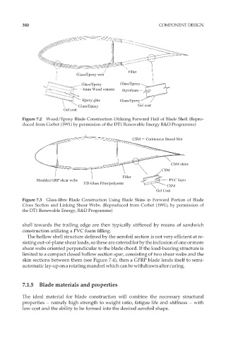
Filler
Glass/Epoxy web
Glass/Epoxy Glass/Epoxy
4mm Wood veneers Styrofoam
Epoxy glue Glass/Epoxy
Glass/Epoxy Gel coat
Gel coat
Figure 7.2 Wood/Epoxy Blade Construction Utilizing Forward Half of Blade Shell (Repro-
duced from Corbet (1991) by permission of the DT1 Renewable Energy R&D Programme)
CSM Continuous Strand Mat
CSM skins
CSM
Filler
Moulded GRP shear webs PVC foam
UD Glass Fibre/polyester
CSM
Gel Coat
Figure 7.3 Glass-fibre Blade Construction Using Blade Skins in Forward Portion of Blade
Cross Section and Linking Shear Webs. (Reproduced from Corbet (1991), by permission of
the DT1 Renewable Energy, R&D Programme)
shell towards the trailing edge are then typically stiffened by means of sandwich
construction utilizing a PVC foam filling.
The hollow shell structure defined by the aerofoil section is not very efficient at re-
sisting out-of-plane shear loads, so these are catered for by the inclusion of one or more
shear webs oriented perpendicular to the blade chord. If the load-bearing structure is
limited to a compact closed hollow section spar, consisting of two shear webs and the
skin sections between them (see Figure 7.4), then a GFRP blade lends itself to semi-
automatic lay-up on a rotatingmandrel which canbe withdrawn after curing.
7.1.5 Blade materials and properties
The ideal material for blade construction will combine the necessary structural
properties – namely high strength to weight ratio, fatigue life and stiffness – with
low cost and the ability to be formed into the desired aerofoil shape.