
Page 487 - Wind Energy Handbook
P. 487
TOWER 461
the extreme load, with the result that the bolts are not subject to fatigue loads.
Unfortunately, apart from the effect of splice plates on the external appearance,
there are practical difficulties of joint assembly, because bolting requires the
provision of some form of personnel access on the outside of the tower. Neverthe-
less splice plates are used on some towers.
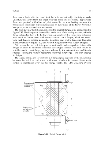
The most popular bolted arrangement is the internal flanged joint as illustrated in
Figure 7.42. The flanges are butt welded to the ends of the mating sections, with the
flange outer edge flush with the tower wall. Alternatively the flange may be formed
with a stub section of tower wall already attached. Such flanges, which are termed
weld neck flanges, provide a smoother transition from wall to flange (as illustrated
in the lower half of Figure 7.42) and result in a higher butt-weld fatigue category.
After assembly, each bolt is torqued or tensioned to induce a preload between the
flanges in order to minimize in-service bolt fatigue stresses. The bolt should be
initially sized to resist the prying force induced by the extreme tower-wall tensile
stresses – taking the fulcrum adjacent to the flange inner edge – and then checked
for fatigue.
The fatigue calculation for the bolts in a flanged joint depends on the relationship
between the bolt load and tower wall stress, which only remains linear while
contact is maintained over the full flange width. The VDI Guideline (Verein
Z
a b
Boundary of
compressed
volume P/ 2 P/ 2
t
R
X
R
t
Equivalent
cylindrical
annulus
P/ 2 P/ 2
x
Weld neck
Z
Figure 7.42 Bolted Flange Joint