
Page 484 - Wind Energy Handbook
P. 484
458 COMPONENT DESIGN
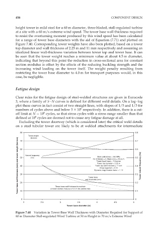
height tower in mild steel for a 60 m diameter, three-bladed, stall-regulated turbine
at a site with a 60 m/s extreme wind speed. The tower base wall thickness required
to resist the overturning moment produced by this wind speed has been calculated
for a range of tower base diameters with the aid of Equation (7.71) and plotted on
Figure 7.40. Corresponding tower weights have also been plotted, based on a tower
top diameter and wall thickness of 2.25 m and 11 mm respectively and assuming an
idealized linear wall-thickness variation between tower top and tower base. It can
be seen that the tower weight reaches a minimum value at about 4.5 m diameter,
indicating that beyond this point the reduction in cross-sectional area for constant
section modulus is offset by the effects of the reducing buckling strength and the
increasing wind loading on the tower itself. The weight penalty resulting from
restricting the tower base diameter to 4.0 m for transport purposes would, in this
case, be negligible.
Fatigue design
Clear rules for the fatigue design of steel-welded structures are given in Eurocode
3, where a family of S–N curves is defined for different weld details. On a log–log
plot these curves in fact consist of two straight lines, with slopes of 1/5 and 1/3 for
6
numbers of cycles above and below 5 3 10 respectively. In addition, there is a cut-
8
off limit at N ¼ 10 cycles, so that stress cycles with a stress range smaller than that
8
defined at 10 cycles are deemed not to cause any fatigue damage at all.
Excluding the tower doorway (which is considered later) the critical weld details
on a steel tubular tower are likely to be at welded attachments for intermediate
80 0.8
Tower weight 0.7
Tower base wall thickness (mm) and tower weight (tonnes) 50 Natural frequency wall thickness (mm) Shear exponent = 0.11 0.5 Tower natural frequency (Hz)
(tonnes)
70
0.6
60
Steel yield stress = 245 MPa
(Hz)
No of blades = 3, Blade area = 50 sq m
Tower head mass = 75 tonnes
Tower top diameter = 2.25 m
Tower top wall thickness = 11 mm
40
0.4
Dynamic magnification factor = 1.12
30
0.3
Tower base
20
Tower base wall thickness to maintain
10
0.1
0 constant section modulus cf 2.5 m dia (dotted line) 0.2
0
2 2.5 3 3.5 4 4.5 5
Tower base diameter (m)
Figure 7.40 Variation in Tower Base Wall Thickness with Diameter Required for Support of
60 m Diameter Stall-regulated Wind Turbine at 50 m Height in 70 m/s Extreme Wind