
Page 485 - Wind Energy Handbook
P. 485
TOWER 459
platform and cable support members and the horizontal welds to the tower base
flange and intermediate bolted flanges. Assuming a full penetration butt weld is
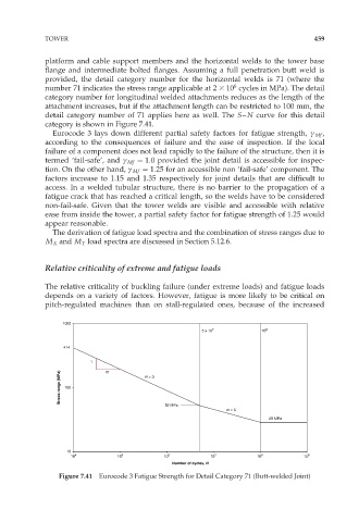
provided, the detail category number for the horizontal welds is 71 (where the
6
number 71 indicates the stress range applicable at 2 3 10 cycles in MPa). The detail
category number for longitudinal welded attachments reduces as the length of the
attachment increases, but if the attachment length can be restricted to 100 mm, the
detail category number of 71 applies here as well. The S–N curve for this detail
category is shown in Figure 7.41.
Eurocode 3 lays down different partial safety factors for fatigue strength, ª Mf ,
according to the consequences of failure and the ease of inspection. If the local
failure of a component does not lead rapidly to the failure of the structure, then it is
termed ‘fail-safe’, and ª Mf ¼ 1:0 provided the joint detail is accessible for inspec-
tion. On the other hand, ª Mf ¼ 1:25 for an accessible non ‘fail-safe’ component. The
factors increase to 1.15 and 1.35 respectively for joint details that are difficult to
access. In a welded tubular structure, there is no barrier to the propagation of a
fatigue crack that has reached a critical length, so the welds have to be considered
non-fail-safe. Given that the tower welds are visible and accessible with relative
ease from inside the tower, a partial safety factor for fatigue strength of 1.25 would
appear reasonable.
The derivation of fatigue load spectra and the combination of stress ranges due to
M X and M Y load spectra are discussed in Section 5.12.6.
Relative criticality of extreme and fatigue loads
The relative criticality of buckling failure (under extreme loads) and fatigue loads
depends on a variety of factors. However, fatigue is more likely to be critical on
pitch-regulated machines than on stall-regulated ones, because of the increased
1000
5 x 10 7 10 8
414
1 m
Stress range (MPa) 100 m = 3
52 MPa
m = 5
29 MPa
10
10 4 10 5 10 6 10 7 10 8 10 9
Number of cycles, N
Figure 7.41 Eurocode 3 Fatigue Strength for Detail Category 71 (Butt-welded Joint)