
Page 483 - Wind Energy Handbook
P. 483
TOWER 457
These values apply if the out-of-plane deviations, w, of the cylinder measured with
either
p ffiffiffiffi
(a) a rod of length L ¼ 4 rt placed vertically, away from welds, or
(b) a circular template of the same length placed horizontally, away from welds, or
(c) a rod of length L ¼ 25t placed vertically across horizontal welds,
do not exceed 1 percent of the respective rod or template length. The value of Æ B is
halved if the maximum value of the imperfection ratio, w=L, is 2 percent, and may
be interpolated for intermediate values of w=L.
The buckling strength, ó u , is then given in terms of the yield strength and the
elastic critical buckling stress (Equation (7.68)) as follows
" #
f y 0:6
ó u ¼ f y 1 0:4123 for Æ B ó cr . f y =2 and ó u ¼ 0:75Æ B ó cr for Æ B ó cr , f y =2
Æ B ó cr
(7:71)
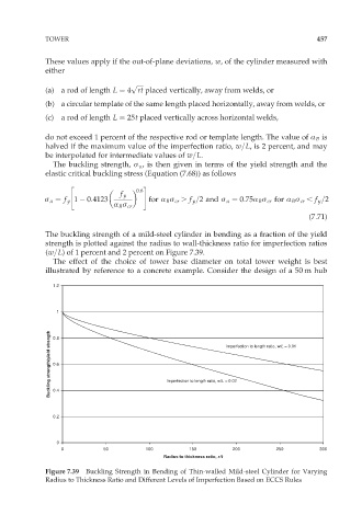
The buckling strength of a mild-steel cylinder in bending as a fraction of the yield
strength is plotted against the radius to wall-thickness ratio for imperfection ratios
(w=L) of 1 percent and 2 percent on Figure 7.39.
The effect of the choice of tower base diameter on total tower weight is best
illustrated by reference to a concrete example. Consider the design of a 50 m hub
1.2
1
Buckling strength/yield strength 0.6 Imperfection to length ratio, w/L = 0.02
0.8
Imperfection to length ratio, w/L = 0.01
0.4
0.2
0
0 50 100 150 200 250 300
Radius to thickness ratio, r/t
Figure 7.39 Buckling Strength in Bending of Thin-walled Mild-steel Cylinder for Varying
Radius to Thickness Ratio and Different Levels of Imperfection Based on ECCS Rules