
Page 98 - Wind Energy Handbook
P. 98
72 AERODYNAMICS OF HORIZONTAL-AXIS WIND TURBINES
1
Blade geometry parameter 0.6
0.8
0.4
0.2
0
0 1 2 3 4 5 6 7 8 9 10
Local speed ratio
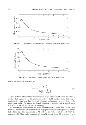
Figure 3.17 Variation of Blade Geometry Parameter with Local Speed Ratio
40
Flow angle in degrees 24
32
16
8
0
0 1 2 3 4 5 6 7 8 9 10
Local speed ratio
Figure 3.18 Variation of Inflow Angle with Local Speed Ratio
which, for optimum operation, is
1
1
tan ö ¼ 3 (3:68a)
2
ºì 1 þ
3º ì
2 2
Close to the blade root the inflow angle is large which could cause the blade to
stall in that region. If the lift coefficient is to be held constant such that drag is
minimized everywhere then the angle of attack Æ also needs to be uniform at the
appropriate value. For a prescribed angle of attack variation the design pitch angle
â ¼ ö Æ of the blade must vary accordingly.
As an example, suppose that the blade aerofoil is NACA 4412, popular for hand-
built wind turbines because the bottom (high pressure) side of the profile is almost
5
flat which facilitates manufacture. At a Reynolds number of about 5 3 10 the
maximum lift/drag ratio occurs at a lift coefficient of about 0.7 and an angle of