
Page 103 - Wind Energy Handbook
P. 103
BLADE GEOMETRY 77
optimal design. A similar result is apparent for the inflow angle distribution where
drag also has little influence, see Figure 3.25. As far as blade design for optimal
operation is concerned drag can be ignored, greatly simplifying the process.
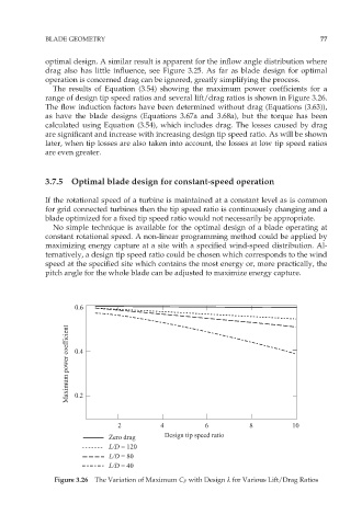
The results of Equation (3.54) showing the maximum power coefficients for a
range of design tip speed ratios and several lift/drag ratios is shown in Figure 3.26.
The flow induction factors have been determined without drag (Equations (3.63)),
as have the blade designs (Equations 3.67a and 3.68a), but the torque has been
calculated using Equation (3.54), which includes drag. The losses caused by drag
are significant and increase with increasing design tip speed ratio. As will be shown
later, when tip losses are also taken into account, the losses at low tip speed ratios
are even greater.
3.7.5 Optimal blade design for constant-speed operation
If the rotational speed of a turbine is maintained at a constant level as is common
for grid connected turbines then the tip speed ratio is continuously changing and a
blade optimized for a fixed tip speed ratio would not necessarily be appropriate.
No simple technique is available for the optimal design of a blade operating at
constant rotational speed. A non-linear programming method could be applied by
maximizing energy capture at a site with a specified wind-speed distribution. Al-
ternatively, a design tip speed ratio could be chosen which corresponds to the wind
speed at the specified site which contains the most energy or, more practically, the
pitch angle for the whole blade can be adjusted to maximize energy capture.
0.6
Maximum power coefficient 0.4
0.2
2 4 6 8 10
Zero drag Design tip speed ratio
L/D = 120
L/D = 80
L/D = 40
Figure 3.26 The Variation of Maximum C P with Design º for Various Lift/Drag Ratios