
Page 99 - Wind Energy Handbook
P. 99
BLADE GEOMETRY 73
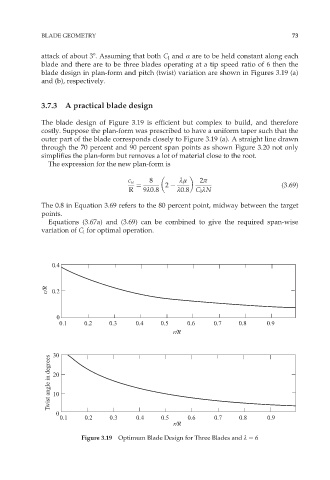
attack of about 38. Assuming that both C l and Æ are to be held constant along each
blade and there are to be three blades operating at a tip speed ratio of 6 then the
blade design in plan-form and pitch (twist) variation are shown in Figures 3.19 (a)
and (b), respectively.
3.7.3 A practical blade design
The blade design of Figure 3.19 is efficient but complex to build, and therefore
costly. Suppose the plan-form was prescribed to have a uniform taper such that the
outer part of the blade corresponds closely to Figure 3.19 (a). A straight line drawn
through the 70 percent and 90 percent span points as shown Figure 3.20 not only
simplifies the plan-form but removes a lot of material close to the root.
The expression for the new plan-form is
c u 8 ºì 2ð
¼ 2 (3:69)
R 9º0:8 º0:8 C l ºN
The 0.8 in Equation 3.69 refers to the 80 percent point, midway between the target
points.
Equations (3.67a) and (3.69) can be combined to give the required span-wise
variation of C l for optimal operation.
0.4
c/R 0.2
0
0.1 0.2 0.3 0.4 0.5 0.6 0.7 0.8 0.9
r/R
30
Twist angle in degrees 20
10
0
0.1 0.2 0.3 0.4 0.5 0.6 0.7 0.8 0.9
r/R
Figure 3.19 Optimum Blade Design for Three Blades and º ¼ 6