
Page 100 - Wind Energy Handbook
P. 100
74 AERODYNAMICS OF HORIZONTAL-AXIS WIND TURBINES
0.4
c/R 0.2
0
0.1 0.2 0.3 0.4 0.5 0.6 0.7 0.8 0.9
r/R
Figure 3.20 Uniform Taper Blade Design for Optimal Operation
8 1
C l ¼ s ffiffiffiffiffiffiffiffiffiffiffiffiffiffiffiffiffiffiffiffiffiffiffiffiffiffiffiffiffiffiffiffiffiffiffiffiffiffiffiffiffiffiffiffiffiffiffiffiffiffiffiffiffiffiffiffiffiffiffiffiffiffiffi
9 2 2
Nc u º 1 2
2 2
1 þº ì 1 þ
2 2
2ð 3 9(º ì )
Close to the blade root the lift coefficient approaches the stalled condition and drag
is high but the penalty is small because the adverse torque is small in that region.
Assuming that stall does not occur and that for the aerofoil in question, which
has a 4 percent camber, the lift coefficient is given approximately by
C l ¼ 0:1(Æ þ 4deg)
where Æ is in degrees, so
C l
Æ ¼ 4deg
0:1
The blade twist distribution can now be determined from Equations (3.68a) and
(3.43).
The twist angle close to the root is still high but lower than for the constant C l
blade.
2
Lift coefficient 1
0
0.2 0.4 0.6 0.8 1
r/R
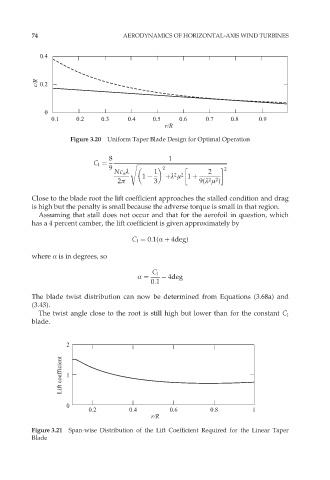
Figure 3.21 Span-wise Distribution of the Lift Coefficient Required for the Linear Taper
Blade