
Page 105 - Wind Energy Handbook
P. 105
THE EFFECTS OF A DISCRETE NUMBER OF BLADES 79
Figure 3.27 Helical Trailing Tip Vortices of a Horizontal Axis Turbine Wake
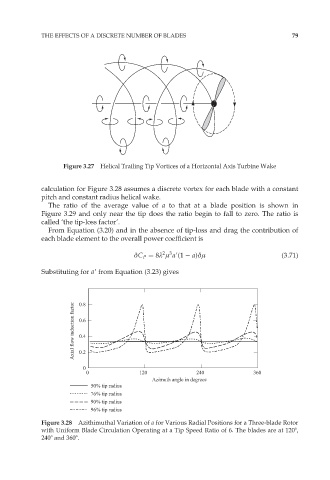
calculation for Figure 3.28 assumes a discrete vortex for each blade with a constant
pitch and constant radius helical wake.
The ratio of the average value of a to that at a blade position is shown in
Figure 3.29 and only near the tip does the ratio begin to fall to zero. The ratio is
called ‘the tip-loss factor’.
From Equation (3.20) and in the absence of tip-loss and drag the contribution of
each blade element to the overall power coefficient is
2 3
äC P ¼ 8º ì a9(1 a)äì (3:71)
Substituting for a9 from Equation (3.23) gives
Axial flow induction factor 0.8
0.6
0.4
0.2
0
0 120 240 360
Azimuth angle in degrees
50% tip radius
76% tip radius
90% tip radius
96% tip radius
Figure 3.28 Azithimuthal Variation of a for Various Radial Positions for a Three-blade Rotor
with Uniform Blade Circulation Operating at a Tip Speed Ratio of 6. The blades are at 1208,
2408 and 3608.