
Page 110 - Wind Energy Handbook
P. 110
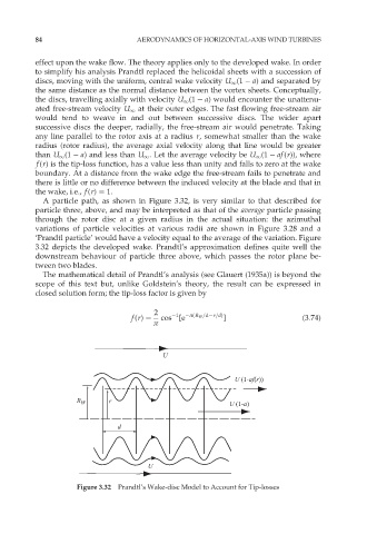
84                         AERODYNAMICS OF HORIZONTAL-AXIS WIND TURBINES


          effect upon the wake flow. The theory applies only to the developed wake. In order
          to simplify his analysis Prandtl replaced the helicoidal sheets with a succession of
          discs, moving with the uniform, central wake velocity U 1 (1   a) and separated by
          the same distance as the normal distance between the vortex sheets. Conceptually,
          the discs, travelling axially with velocity U 1 (1   a) would encounter the unattenu-
          ated free-stream velocity U 1 at their outer edges. The fast flowing free-stream air
          would tend to weave in and out between successive discs. The wider apart
          successive discs the deeper, radially, the free-stream air would penetrate. Taking
          any line parallel to the rotor axis at a radius r, somewhat smaller than the wake
          radius (rotor radius), the average axial velocity along that line would be greater
          than U 1 (1   a) and less than U 1 . Let the average velocity be U 1 (1   af(r)), where
          f(r) is the tip-loss function, has a value less than unity and falls to zero at the wake
          boundary. At a distance from the wake edge the free-stream fails to penetrate and
          there is little or no difference between the induced velocity at the blade and that in
          the wake, i.e., f(r) ¼ 1.
            A particle path, as shown in Figure 3.32, is very similar to that described for
          particle three, above, and may be interpreted as that of the average particle passing
          through the rotor disc at a given radius in the actual situation: the azimuthal
          variations of particle velocities at various radii are shown in Figure 3.28 and a
          ‘Prandtl particle’ would have a velocity equal to the average of the variation. Figure
          3.32 depicts the developed wake. Prandtl’s approximation defines quite well the
          downstream behaviour of particle three above, which passes the rotor plane be-
          tween two blades.
            The mathematical detail of Prandtl’s analysis (see Glauert (1935a)) is beyond the
          scope of this text but, unlike Goldstein’s theory, the result can be expressed in
          closed solution form; the tip-loss factor is given by

                                         2
                                               1
                                   f(r) ¼  cos [e  ð(R W =d r=d) ]             (3:74)
                                         ð


                                           U


                                                              U (1-af(r))

                     R W     r                               U (1-a)


                                d


                                       U

                     Figure 3.32  Prandtl’s Wake-disc Model to Account for Tip-losses