
Page 115 - Wind Energy Handbook
P. 115
THE EFFECTS OF A DISCRETE NUMBER OF BLADES 89
q ffiffiffiffiffiffiffiffiffiffiffiffiffiffiffiffiffiffiffiffiffiffi
1 1 1
a ¼ þ f 1 f þ f 2 (3:84)
3 3 3
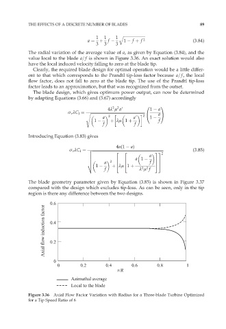
The radial variation of the average value of a, as given by Equation (3.84), and the
value local to the blade a=f is shown in Figure 3.36. An exact solution would also
have the local induced velocity falling to zero at the blade tip.
Clearly, the required blade design for optimal operation would be a little differ-
ent to that which corresponds to the Prandtl tip-loss factor because a=f, the local
flow factor, does not fall to zero at the blade tip. The use of the Prandtl tip-loss
factor leads to an approximation, but that was recognized from the outset.
The blade design, which gives optimum power output, can now be determined
by adapting Equations (3.66) and (3.67) accordingly
0 1
2 2
4º ì a9 1 a
ó r ºC l ¼ s ffiffiffiffiffiffiffiffiffiffiffiffiffiffiffiffiffiffiffiffiffiffiffiffiffiffiffiffiffiffiffiffiffiffiffiffiffiffiffiffiffiffiffiffiffiffiffiffiffiffiffiffiffiffiffi
@ aA
2
a 2 a9 1
1 þ ºì 1 þ f
f f
Introducing Equation (3.83) gives
4a(1 a)
ó r ºC l ¼ v ffiffiffiffiffiffiffiffiffiffiffiffiffiffiffiffiffiffiffiffiffiffiffiffiffiffiffiffiffiffiffiffiffiffiffiffiffiffiffiffiffiffiffiffiffiffiffiffiffiffiffiffiffiffiffiffiffiffiffiffiffiffiffiffiffiffiffiffiffiffiffiffi (3:85)
u 2 2 33 2
u a
u a 1
u 2 6 6 77
t a 4 4 f 55
1 þ ºì 1 þ
2 2
f º ì f
The blade geometry parameter given by Equation (3.85) is shown in Figure 3.37
compared with the design which excludes tip-loss. As can be seen, only in the tip
region is there any difference between the two designs.
0.6
Axial flow induction factor 0.4
0.2
0
0 0.2 0.4 0.6 0.8 1
r/R
Azimuthal average
Local to the blade
Figure 3.36 Axial Flow Factor Variation with Radius for a Three-blade Turbine Optimized
for a Tip Speed Ratio of 6