Page 120 - Wind Energy Handbook
P. 120

94                         AERODYNAMICS OF HORIZONTAL-AXIS WIND TURBINES


                                              0.4
             1.5


                                              0.3
               1                                                                12%
            Lift coefficient  0.5            Drag coefficient  0.2              15%

                                                                                18%
                                                                                21%
                                                                                25%

               0                              0.1


             -0.5                               0
               -10         0           10          20         30  -10         0           10          20         30
                       Angle of attack                  Angle of attack

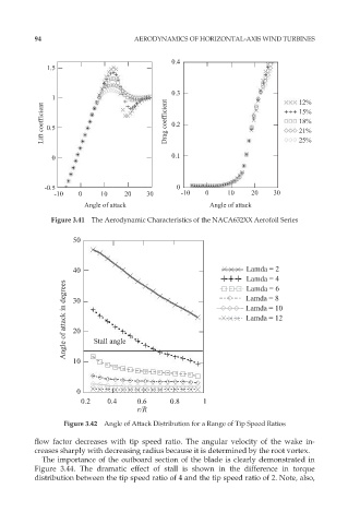
               Figure 3.41  The Aerodynamic Characteristics of the NACA632XX Aerofoil Series

                    50


                    40                                            Lamda = 2
                                                                  Lamda = 4
                  Angle of attack in degrees  30                  Lamda = 10
                                                                  Lamda = 6
                                                                  Lamda = 8

                                                                  Lamda = 12
                    20


                    10    Stall angle


                     0
                      0.2         0.4    0.6       0.8          1
                                     r/R

                  Figure 3.42  Angle of Attack Distribution for a Range of Tip Speed Ratios
          flow factor decreases with tip speed ratio. The angular velocity of the wake in-
          creases sharply with decreasing radius because it is determined by the root vortex.
            The importance of the outboard section of the blade is clearly demonstrated in
          Figure 3.44. The dramatic effect of stall is shown in the difference in torque
          distribution between the tip speed ratio of 4 and the tip speed ratio of 2. Note, also,
   115   116   117   118   119   120   121   122   123   124   125