
Page 125 - Wind Energy Handbook
P. 125
THE AERODYNAMICS OF A WIND TURBINE IN STEADY YAW 99
be capable of determining the induced velocity at each blade element position to a
satisfactory accuracy. The satisfactory calculation of blade forces is as important as
the estimation of power.
3.10.2 Glauert’s momentum theory for the yawed rotor
Glauert (1926) was primarily interested in the autogyro which is an aircraft with a
rotor to provide lift and a conventional propeller to provide forward thrust. The
lifting rotor has a rotational axis which inclines backwards from the vertical and by
virtue of the forward speed of the aircraft air flows through the rotor disc causing it
to rotate and to provide an upward thrust. Thus, the autogyro rotor is just like a
wind turbine rotor in yaw, when in forward flight. At high forward speeds the yaw
angle is large but in a power off vertical descent the yaw angle is zero.
Glauert maintained that at high forward speed the rotor disc, which is operating
at a high tip speed ratio, is like a wing of circular plan-form at a small angle of
attack (large yaw angle) and so the thrust on the disc is the lift on the circular wing.
Simple lifting line wing theory (see Prandtl and Tietjens, 1957) states that the down-
wash (induced velocity) at the wing, caused by the trailing vortex system, is
uniform over the wing span (transverse diameter of the disc) for a wing with an
elliptical plan-form and this would include the circular plan-form of the autogyro
rotor.
The theory gives the uniform (average) induced velocity as
2L
u ¼ (3:92)
2
ð(2R) rV
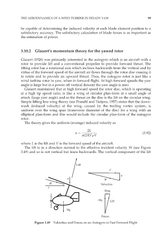
where L is the lift and V is the forward speed of the aircraft.
The lift is in a direction normal to the effective incident velocity W (see Figure
3.49) and so is not vertical but leans backwards. The vertical component of the lift
Lift
V
u
u
W
W Velocities
V
Drag
-Mg Lift
Mg
Forces
Figure 3.49 Velocities and Forces on an Autogyro in Fast Forward Flight