
Page 129 - Wind Energy Handbook
P. 129
THE AERODYNAMICS OF A WIND TURBINE IN STEADY YAW 103
where ł is the blade azimuth angle measured in the direction of rotation, 08 being
when the blade is normal to the flight direction (or when the wind turbine blade is
vertically upwards), and u 1 is the amplitude of the non-uniform component which
is dependent on the yaw angle. There would, of course, need to be induced
velocities parallel to the plane of the rotor disc but these are of secondary
importance; the normal induced velocity has a much greater influence on the blade
angle of attack than the in-plane component and therefore a much greater influence
on blade element forces.
The value of u 1 in Equation (3.107) cannot be determined from momentum theory
but Glauert suggested that it would be of the same order of magnitude as u 0 . The
total induced velocity, normal to the rotor plane, may then be written as
r
u ¼ u 0 1 þ K sin ł (3:108)
R
The value of K must depend upon the yaw angle.
3.10.3 Vortex cylinder model of the yawed actuator disc
The vortex theory for the non-yawed rotor given in Section 3.4 was demonstrated to
be equivalent to the momentum theory in its main results but, in addition, was
shown to give much more detail about the flow-field. As the momentum theories of
Sections 3.10.1 and 3.10.2 yield very limited results using the vortex approach for the
yawed rotor may also prove to be useful, giving more flow structure detail than the
momentum theory and, perhaps, a means of allying it with the blade element theory.
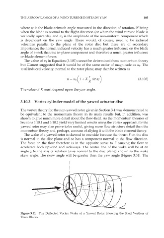
The wake of a yawed rotor is skewed to one side because the thrust F on the disc
is normal to the disc plane and so has a component normal to the flow direction.
The force on the flow therefore is in the opposite sense to F causing the flow to
accelerate both upwind and sideways. The centre line of the wake will be at an
angle ÷ to the axis of rotation (axis normal to the disc plane) known as the wake
skew angle. The skew angle will be greater than the yaw angle (Figure 3.51). The
χ
γ
Figure 3.51 The Deflected Vortex Wake of a Yawed Rotor Showing the Shed Vortices of
Three Blades