
Page 133 - Wind Energy Handbook
P. 133
THE AERODYNAMICS OF A WIND TURBINE IN STEADY YAW 107
3.10.4 Flow expansion
The induced velocity component parallel to the skewed axis of the wake is uniform
over the disc with a value aU 1 , as can be deduced from Figure 3.54. The induced
horizontal velocity, normal to the skewed axis of the wake is also uniform over the
area of the disc with a value a tan(÷=2)U 1 .
In addition to the uniform induced velocities of Figure 3.54 the expansion of the
flow gives rise to velocities in the y and z directions, respectively (i.e., directions in
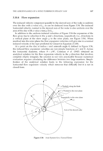
a vertical plane at the skew angle ÷ to the rotor plane, see Figure 3.56). When
resolved into the rotor plane the flow expansion velocities will give rise to a normal
induced velocity of the type predicted by Glauert in Equation (3.108).
At a point on the disc at radius r and azimuth angle Ł, defined in Figure 3.56,
the induced flow expansion velocities are non-simple functions of r and Ł. Across
the horizontal diameter, where Ł ¼ 908, Coleman et al. (1945) obtained an
analytical solution for the flow expansion velocity in the y direction that involves
complete elliptic integrals; the solution is not very practicable because numerical
evaluation requires calculating the difference between two large numbers. Simpli-
fication of the analytical solution leads to the following expression for the
horizontal flow expansion velocity which removes that difficulty but it is not in
closed form.
z,w
z'', w''Radially along the blade
x'', u''Normal to the rotor plane
ψ
y,v χ
r
Tangentially in the rotor plane
x,u
y' χ y'',v''
Axis of the skewed wake
U Ω
γ
Figure 3.56 Axis System for a Yawed Rotor