
Page 135 - Wind Energy Handbook
P. 135
THE AERODYNAMICS OF A WIND TURBINE IN STEADY YAW 109
velocity is of less importance than the horizontal velocity in determining the
aerodynamic behaviour of the yawed rotor.
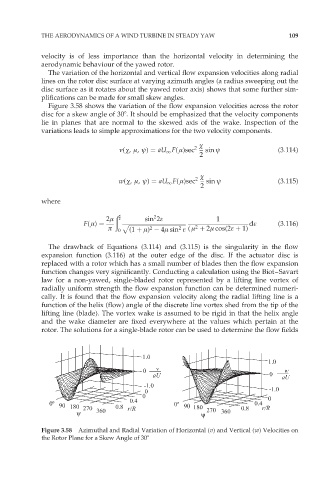
The variation of the horizontal and vertical flow expansion velocities along radial
lines on the rotor disc surface at varying azimuth angles (a radius sweeping out the
disc surface as it rotates about the yawed rotor axis) shows that some further sim-
plifications can be made for small skew angles.
Figure 3.58 shows the variation of the flow expansion velocities across the rotor
disc for a skew angle of 308. It should be emphasized that the velocity components
lie in planes that are normal to the skewed axis of the wake. Inspection of the
variations leads to simple approximations for the two velocity components.
÷
í(÷, ì, ł) ¼ aU 1 F( ì)sec 2 sin ł (3:114)
2
÷
w(÷, ì, ł) ¼ aU 1 F( ì)sec 2 sin ł (3:115)
2
where
2ì ðð 2 sin 2å 1
2
F( ì) ¼ p ffiffiffiffiffiffiffiffiffiffiffiffiffiffiffiffiffiffiffiffiffiffiffiffiffiffiffiffiffiffiffiffiffiffiffiffiffiffiffiffi då (3:116)
ð 0 (1 þ ì) 4ì sin å ( ì þ 2ì cos(2å þ 1)
2
2
2
The drawback of Equations (3.114) and (3.115) is the singularity in the flow
expansion function (3.116) at the outer edge of the disc. If the actuator disc is
replaced with a rotor which has a small number of blades then the flow expansion
function changes very significantly. Conducting a calculation using the Biot–Savart
law for a non-yawed, single-bladed rotor represented by a lifting line vortex of
radially uniform strength the flow expansion function can be determined numeri-
cally. It is found that the flow expansion velocity along the radial lifting line is a
function of the helix (flow) angle of the discrete line vortex shed from the tip of the
lifting line (blade). The vortex wake is assumed to be rigid in that the helix angle
and the wake diameter are fixed everywhere at the values which pertain at the
rotor. The solutions for a single-blade rotor can be used to determine the flow fields
Figure 3.58 Azimuthal and Radial Variation of Horizontal (v) and Vertical (w) Velocities on
the Rotor Plane for a Skew Angle of 308