
Page 134 - Wind Energy Handbook
P. 134
108 AERODYNAMICS OF HORIZONTAL-AXIS WIND TURBINES
í(÷, ì) ¼
ðð 2
2ì sin ŁaU 1 2 sin 2å 1
p ffiffiffiffiffiffiffiffiffiffiffiffiffiffiffiffiffiffiffiffiffiffiffiffiffiffiffiffiffiffiffiffiffiffiffiffiffiffiffiffi då (3:113)
ð 0 (1 þ ì) 4ì sin å [( ì þ cos 2å) ]cos ÷ þ sin 2å
2
2
2
2
2
where ì ¼ r=R, å is a parameter arising from the elliptic integrals, which is elimi-
nated from the function by the definite integral, and aU 1 is the average induced
velocity as previously defined. An important feature of Equation (3.113) is that the
flow expansion velocity is proportional to the average axial flow induction factor.
Furthermore, if Equation (3.113) is divided by sec(÷=2) 2 the result is almost
independent of the skew angle ÷. Let
í(÷, ì)
÷
sec sin ł aU 1
2
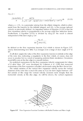
be defined as the flow expansion function F( ì) which is shown in Figure 3.57,
clearly demonstrating how little F( ì) changes over a range of skew angle of 08 to
608.
At all skew angles the value of the flow expansion function is infinite at the edge
of the rotor disc, indicating a singularity in the flow which, of course, does not
occur in practice but is a result of assuming uniform blade circulation. Circulation
must fall to zero at the disc edge in a smooth fashion.
No analytical expressions for the flow expansion velocity components for values
of Ł other than 908 were developed by Coleman et al. (1945) but numerical
evaluations of the flow expansion velocities can be made using the Biot–Savart law.
The radial variation of the vertical flow expansion velocity across the vertical
diameter of the rotor disc is much the same as F( ì) for skew angles between 458
but outside of this range the vertical velocity increases more sharply than the
horizontal velocity at the disc edge. As will be shown, the vertical expansion
F(µ)
1
60° 0.5
30° 0.8
0° 0.2 0.4 0.6
0 µ
Figure 3.57 Flow Expansion Function Variation with Radial Position and Skew Angle