
Page 136 - Wind Energy Handbook
P. 136
110 AERODYNAMICS OF HORIZONTAL-AXIS WIND TURBINES
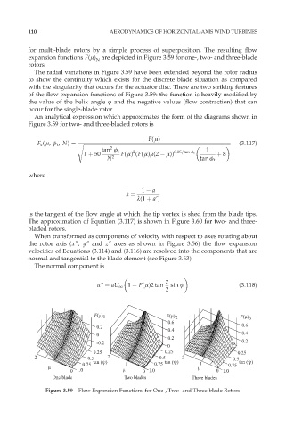
for multi-blade rotors by a simple process of superposition. The resulting flow
expansion functions F(ì) are depicted in Figure 3.59 for one-, two- and three-blade
N
rotors.
The radial variations in Figure 3.59 have been extended beyond the rotor radius
to show the continuity which exists for the discrete blade situation as compared
with the singularity that occurs for the actuator disc. There are two striking features
of the flow expansion functions of Figure 3.59: the function is heavily modified by
the value of the helix angle ö and the negative values (flow contraction) that can
occur for the single-blade rotor.
An analytical expression which approximates the form of the diagrams shown in
Figure 3.59 for two- and three-bladed rotors is
F( ì)
F a ( ì, ö t , N) ¼ s ffiffiffiffiffiffiffiffiffiffiffiffiffiffiffiffiffiffiffiffiffiffiffiffiffiffiffiffiffiffiffiffiffiffiffiffiffiffiffiffiffiffiffiffiffiffiffiffiffiffiffiffiffiffiffiffiffiffiffiffiffiffiffiffiffiffiffiffiffiffiffiffiffiffiffiffiffiffiffiffiffiffiffiffiffiffiffiffiffiffiffiffiffiffiffiffiffiffiffiffiffiffiffiffiffiffiffiffiffiffiffiffiffiffiffi (3:117)
2
tan ö t 2 1
1 þ 50 F( ì) (F( ì)ì(2 ì)) 0:05=tan ö t þ 8
N 2 tan ö t
where
1 a
k ¼
º(1 þ a9)
is the tangent of the flow angle at which the tip vortex is shed from the blade tips.
The approximation of Equation (3.117) is shown in Figure 3.60 for two- and three-
bladed rotors.
When transformed as components of velocity with respect to axes rotating about
the rotor axis (x", y" and z" axes as shown in Figure 3.56) the flow expansion
velocities of Equations (3.114) and (3.116) are resolved into the components that are
normal and tangential to the blade element (see Figure 3.63).
The normal component is
÷
u0 ¼ aU 1 1 þ F( ì)2 tan sin ł (3:118)
2
F(µ) 1 F(µ) 2 F(µ) 3
0.6
0.2 0.6
0.4
0 0.4
0.2
-0.2 0.2
0
0.25 0.25 0.25
2 0.5 2 0.5 2 0.5
1 0.75 tan (ψ) 1 0.75 tan (ψ) 1 0.75 tan (ψ)
µ µ
0 1.0 µ 0 1.0 0 1.0
One blade Two blades Three blades
Figure 3.59 Flow Expansion Functions for One-, Two- and Three-blade Rotors