
Page 141 - Wind Energy Handbook
P. 141
THE AERODYNAMICS OF A WIND TURBINE IN STEADY YAW 115
Thus the wake rotation produces two velocity components, one in the rotor plane
and one normal to the rotor plane; there is no radial component.
3.10.7 The blade element theory for a turbine rotor in steady yaw
There is doubt about the applicability of the blade element theory in the case of a
yawed turbine because the flow, local to a blade element, is unsteady and because
the theory representing the vortex half of the equation, which replaces the momen-
tum theory, is incomplete in this respect. However, it is not clear how large or
significant are the unsteady forces. If the unsteady forces are large then the blade
element theory is inapplicable and the results of applying the theory will bear no
relation to measured results. If the unsteady forces are small then there should be
some correspondence with actual values. In a steady yawed condition the flow
velocities at a point on the rotor disc do not change with time, if an infinity of blades
is assumed, and so there is no added mass term to consider. However, the change
of angle of attack with time at a point on the blade does mean that the two
dimensional lift force should really be modified by a lift deficiency function similar
to that determined by Theodorsen (1935) for the rectilinear wake of sinusoidally
pitching aerofoil.
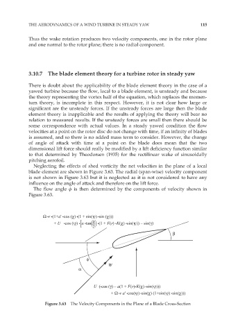
Neglecting the effects of shed vorticity the net velocities in the plane of a local
blade element are shown in Figure 3.63. The radial (span-wise) velocity component
is not shown in Figure 3.63 but it is neglected as it is not considered to have any
influence on the angle of attack and therefore on the lift force.
The flow angle ö is then determined by the components of velocity shown in
Figure 3.63.
Ω •r •(1+a' •cos (χ) •(1 + sin(ψ) •sin (χ)))
χ
+ U •cos (ψ) •[ a •tan( ) •(1 + F(r) •K(χ) •sin(ψ)) – sin(γ)
| 2
β
φ
W
α
U (•cos (γ) – a(1 + F(r)•K(χ) •sin(ψ)))
+ Ω •r a' •cos(ψ) •sin(χ) (1+sin(ψ) •sin(χ)))
Figure 3.63 The Velocity Components in the Plane of a Blade Cross-Section