
Page 145 - Wind Energy Handbook
P. 145
THE AERODYNAMICS OF A WIND TURBINE IN STEADY YAW 119
2
W 2 (cos ª a)
¼ (3:139)
U 2 þ ºìa9 cos ł sin ÷(1 þ sin ł sin ÷)
1
2 3 2
(ºì(1 þ a9 cos ÷(1 þ sin ł sin ÷)))
6 7
þ 4 ÷ 5
þ cos ł a tan sin ª
2
Note that the flow expansion terms, those terms that involve F( ì)K(÷), have been
excluded from the velocity components in Equation (3.139) because flow expansion
is not present in the wake and so there is no associated momentum change. The
blade force, which arises from the flow expansion velocity, is balanced in the wake
by pressure forces acting on the sides of the stream-tubes, which have a stream-
wise component because the stream-tubes are expanding.
Equations (3.137) and (3.138) can be solved by iteration, the integrals being
determined numerically. Initial values are chosen for a and a9, usually zero. For a
given blade geometry, at each blade element position ì and at each blade azimuth
position ł, the flow angle ö is calculated from Equation (3.131), which have been
suitably modified to remove the flow expansion velocity, in accordance with Equa-
tion (3.139). Then, knowing the blade pitch angle â at the blade element, the local
angle of attack can be found. Lift and drag coefficients are obtained from tabulated
aerofoil data. Once an annular ring (constant ì) has been completed the integrals
are calculated. The new value of axial flow factor a is determined from Equation
(3.137) and then the tangential flow factor a9 is found from Equation (3.138).
Iteration proceeds for the same annular ring until a satisfactory convergence is
achieved before moving to the next annular ring (value of ì).
Although the theory supports only the determination of azimuthally averaged
values of the axial flow induced velocity, once the averaged tangential flow
induction factors have been calculated the elemental form of the momentum equa-
tion (3.134) and the blade element force (Equation (3.133)) can be employed to yield
values of a which vary with azimuth.
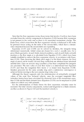
For the determination of blade forces the flow expansion velocities must be
included. The total velocity components, normal and tangential to a blade element,
are then as shown in Figure 3.63 and the resultant velocity is
2
W 2 (cos ª a(1 þ F( ì)K(÷)sin ł))
¼ (3:139a)
U 2 þ ºìa9 cos ł sin ÷(1 þ sin ł sin ÷)
1
2 3 2
(ºì(1 þ a9 cos ÷(1 þ sin ł sin ÷)))
6 7
þ 4 ÷ 5
þ cos ł a tan (1 þ F( ì)K(÷)sin ł) sin ª
2