
Page 128 - Wind Energy Handbook
P. 128
102 AERODYNAMICS OF HORIZONTAL-AXIS WIND TURBINES
p ffiffiffiffiffiffiffiffiffiffiffiffiffiffiffiffiffiffiffiffiffiffiffiffiffiffiffiffiffiffiffiffiffiffiffiffi
C T ¼ 4a 1 a(2 cos ª a) (3:105)
The power developed is a scalar quantity and so is the scalar product of the thrust
force and the resultant velocity at the disc W. Hence, the power coefficient is
p ffiffiffiffiffiffiffiffiffiffiffiffiffiffiffiffiffiffiffiffiffiffiffiffiffiffiffiffiffiffiffiffiffiffiffiffi
C P ¼ 4a 1 a(2 cos ª a)(cos ª a) (3:106)
However, as some of the thrust is attributable to lift on the rotor disc acting as a
circular wing that lift will not extract power from the wind because the net velocity
field associated with the lift does not give rise to a flow through the rotor disc. Only
that proportion of the thrust which arises from net flow through the disc will extract
energy from the flow. Consequently, the axial momentum theory is more likely to
estimate the power extraction correctly, whereas the Glauert theory is more likely
to estimate the thrust correctly.
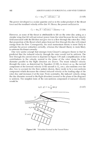
One very useful concept that emerges from Glauert’s autogyro theory is that he
predicted that the induced velocity through the rotor would not be uniform. The
flow through the yawed rotor is depicted in Figure 3.50 and a simplification of the
contributions to the velocity normal to the plane of the rotor along the rotor
diameter parallel to the flight direction are shown. The mean induced velocity
through the rotor, as determined by Equation (3.100), is shown as u 0 , the normal
component of the forward velocity of the aircraft is U 1 cos ª, also uniform over the
disc, but, to account for the flow pattern shown, there needs to be a non-uniform
component which decreases the normal induced velocity at the leading edge of the
rotor disc and increases it at the rear. From symmetry, the induced velocity along
the disc diameter normal to the flight direction (normal to the plane of the diagram)
is uniform. The simplest form of the non-uniform component of induced velocity
would be
r
u 1 (r, ł) ¼ u 1 sin ł (3:107)
R
U α
γ
u o
u (r,ψ)
o
U cosγ
Figure 3.50 Velocities Normal to the Yawed Rotor