
Page 124 - Wind Energy Handbook
P. 124
98 AERODYNAMICS OF HORIZONTAL-AXIS WIND TURBINES
direction is equal to the mass flow rate through the rotor disc times the change in
velocity normal to the plane of the rotor
F ¼ rA d U 1 (cos ª a)2aU 1 (3:88)
Therefore the thrust coefficient is
C T ¼ 4a(cos ª a) (3:89)
and the power developed is
FU 1 (cos ª a)
C P ¼ 4a(cos ª a) 2 (3:90)
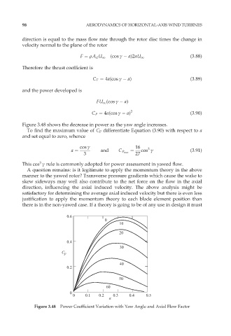
Figure 3.48 shows the decrease in power as the yaw angle increases.
To find the maximum value of C P differentiate Equation (3.90) with respect to a
and set equal to zero, whence
cos ª 16
3
a ¼ and C P max ¼ cos ª (3:91)
3 27
3
This cos ª rule is commonly adopted for power assessment in yawed flow.
A question remains: is it legitimate to apply the momentum theory in the above
manner to the yawed rotor? Transverse pressure gradients which cause the wake to
skew sideways may well also contribute to the net force on the flow in the axial
direction, influencing the axial induced velocity. The above analysis might be
satisfactory for determining the average axial induced velocity but there is even less
justification to apply the momentum theory to each blade element position than
there is in the non-yawed case. If a theory is going to be of any use in design it must
0.6
0
10
20
0.4
30
C p
40
0.2
50
60
0
0 0.1 0.2 0.3 0.4 0.5
a
Figure 3.48 Power Coefficient Variation with Yaw Angle and Axial Flow Factor