
Page 119 - Wind Energy Handbook
P. 119
CALCULATED RESULTS FOR AN ACTUAL TURBINE 93
average value of a which should determine at which stage the momentum theory
breaks down.
3.9 Calculated Results for an Actual Turbine
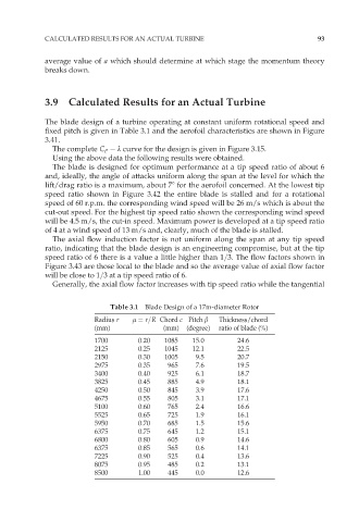
The blade design of a turbine operating at constant uniform rotational speed and
fixed pitch is given in Table 3.1 and the aerofoil characteristics are shown in Figure
3.41.
The complete C P º curve for the design is given in Figure 3.15.
Using the above data the following results were obtained.
The blade is designed for optimum performance at a tip speed ratio of about 6
and, ideally, the angle of attacks uniform along the span at the level for which the
lift/drag ratio is a maximum, about 78 for the aerofoil concerned. At the lowest tip
speed ratio shown in Figure 3.42 the entire blade is stalled and for a rotational
speed of 60 r.p.m. the corresponding wind speed will be 26 m/s which is about the
cut-out speed. For the highest tip speed ratio shown the corresponding wind speed
will be 4.5 m/s, the cut-in speed. Maximum power is developed at a tip speed ratio
of 4 at a wind speed of 13 m/s and, clearly, much of the blade is stalled.
The axial flow induction factor is not uniform along the span at any tip speed
ratio, indicating that the blade design is an engineering compromise, but at the tip
speed ratio of 6 there is a value a little higher than 1=3. The flow factors shown in
Figure 3.43 are those local to the blade and so the average value of axial flow factor
will be close to 1=3 at a tip speed ratio of 6.
Generally, the axial flow factor increases with tip speed ratio while the tangential
Table 3.1 Blade Design of a 17m-diameter Rotor
Radius r ì ¼ r=R Chord c Pitch â Thickness/chord
(mm) (mm) (degree) ratio of blade (%)
1700 0.20 1085 15.0 24.6
2125 0.25 1045 12.1 22.5
2150 0.30 1005 9.5 20.7
2975 0.35 965 7.6 19.5
3400 0.40 925 6.1 18.7
3825 0.45 885 4.9 18.1
4250 0.50 845 3.9 17.6
4675 0.55 805 3.1 17.1
5100 0.60 765 2.4 16.6
5525 0.65 725 1.9 16.1
5950 0.70 685 1.5 15.6
6375 0.75 645 1.2 15.1
6800 0.80 605 0.9 14.6
6375 0.85 565 0.6 14.1
7225 0.90 525 0.4 13.6
8075 0.95 485 0.2 13.1
8500 1.00 445 0.0 12.6