
Page 118 - Wind Energy Handbook
P. 118
92 AERODYNAMICS OF HORIZONTAL-AXIS WIND TURBINES
0.6
Maximum power coefficient 0.4
0.5
0.3
0.2
0 2 4 6 8 10
Design tip speed ratio
Zero drag
L/D = 120
L/D = 80
L/D = 40
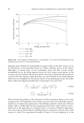
Figure 3.40 The Variation of Maximum C P with Design º for Various Lift/Drag Ratios and
Including Tip-losses for a Three-bladed Rotor
depends upon whether the azimuthally averaged values of the flow factors are to
be determined or the maximum (local to a blade element) values. If the former
alternative is chosen then, in the momentum terms the flow factors remain
unmodified but in the blade element terms the flow factors must appear as the
average values divided by the tip-loss factor. Choosing to determine the maximum
values of the flow factors means that they are not modified in the blade element
terms but are multiplied by the tip-loss factor in the momentum terms. The latter
choice allows the simplest modification of Equations (3.51) and (3.52).
af ó r ó r 2 1 a
¼ C x C y (3:51b)
2
2
1 a 4 sin ö 4 sin ö 1 af
a9 f ó r 1 a
¼ (3:52a)
1 þ a9 4 sin ö cos ö 1 af
There remains the problem of the breakdown of the momentum theory when wake
mixing occurs. The helicoidal vortex sheets may not exist and so Prandtl’s approx-
imation is not physically appropriate. Nevertheless particles which pass between
blades will no doubt still lose less momentum than those which interact with a
blade and so the application of a tip-loss factor is necessary. Prandtl’s approxima-
tion is the only practical method available and so is commonly used. In view of the
manner in which the experimental results of Figure 3.16 were gathered it is the