
Page 121 - Wind Energy Handbook
P. 121
CALCULATED RESULTS FOR AN ACTUAL TURBINE 95
0.8 0.15
0.6 0.1
Axial flow induction factor 0.4 Tangential flow induction factor 0.05
0.2
0 0
0.2 0.4 0.6 0.8 1 0.2 0.4 0.6 0.8 1
r/R r/R
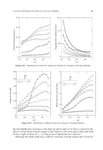
Figure 3.43 Distribution of the Flow Induction Factors for a Range of Tip Speed Ratios
0.6 8
dQ
dr dF
0.5 dr
1
p U s R 2
2
2 6 1 p U s R 2
2
0.4 2
Torque per unit span 0.3 Blade axial force per unit span 4
0.2
0.1 2
0 0
0.2 0.4 0.6 0.8 1 0.2 0.4 0.6 0.8 1
r/R r/R
Figure 3.44 Distribution of Blade Loads for a Range of Tip Speed Ratios
the flat distribution of torque at the high tip speed ratio of 12; this is caused by the
effect of drag which reduces torque as the square of the local speed ratio and with
the low angle of attack at º ¼ 12 drag causes a significant loss of power.
Although the blade axial force coefficient increases with tip speed ratio it must be