
Page 101 - Wind Energy Handbook
P. 101
BLADE GEOMETRY 75
30
Twist angle in degrees 20
10
0
0.1 0.2 0.3 0.4 0.5 0.6 0.7 0.8 0.9
r/R
Figure 3.22 Span-wise Distribution of the Twist Required for the Linear Taper Blade
3.7.4 Effects of drag on optimal blade design
If, despite the views of Wilson and Lissaman (1974), see Section 3.5.3, the effects of
drag are included in the determination of the flow induction factors we must return
to Equation (3.46) and follow the same procedure as described for the drag free
case.
In the current context the effects of drag are dependent upon the magnitude of
the lift/drag ratio which, in turn, depends on the aerofoil profile but largely on
Reynolds number and on the surface roughness of the blade. A high value of lift/
drag ratio would be about 150, whereas a low value would be about 40.
Unfortunately, with the inclusion of drag, the algebra of the analysis is complex.
Polynomial equations have to be solved for both a and a9. The details of the analysis
are left for the reader to discover.
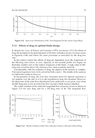
In the presence of drag, the axial flow induction factor for optimal operation is
not uniform over the disc as it is in the hypothetical drag free situation. However,
the departure of the axial flow distribution from uniformity is not great, even when
the lift/drag ratio is low provided the flow around a blade remains attached.
The radial variation of the axial and tangential flow induction factors is shown in
Figure 3.23 for zero drag and for a lift/drag ratio of 40. The tangential flow
0.4
0.1
Axial flow induction factor 0.3 Tangental flow induction factor 0.08
0.06
0.2
0.04
0.1
0 0.02
0 1 2 3 4 5 6 7 8 9 10 0
0 1 2 3 4 5 6 7 8 9 10
Local speed ratio
Zero drag Local speed ratio
L/D = 40
Figure 3.23 Radial Variation of the Flow Induction Factors with and without Drag