
Page 25 - Wire Bonding in Microelectronics
P. 25
4 Cha pte r O n e
1
2
Capillary
tool
3
Gold
wire
Spark US energy,
EFO pressure,
wand
and heat
to form ball
Chip
bond pad bond
4
5
Loop formation
Ball
bond
Package
bond pad
7
6
US energy, Crescent or
pressure, stitch bond
and heat
Package to form tail
bond pad bond
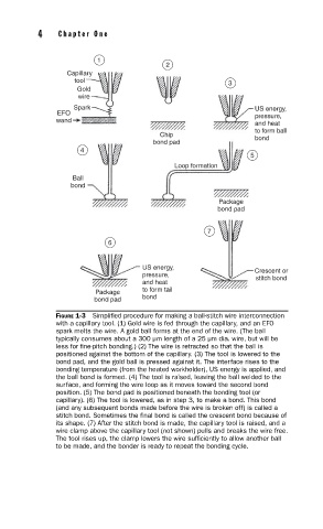
FIGURE 1-3 Simplifi ed procedure for making a ball-stitch wire interconnection
with a capillary tool. (1) Gold wire is fed through the capillary, and an EFO
spark melts the wire. A gold ball forms at the end of the wire. (The ball
typically consumes about a 300 µm length of a 25 µm dia. wire, but will be
less for fi ne-pitch bonding.) (2) The wire is retracted so that the ball is
positioned against the bottom of the capillary. (3) The tool is lowered to the
bond pad, and the gold ball is pressed against it. The interface rises to the
bonding temperature (from the heated workholder), US energy is applied, and
the ball bond is formed. (4) The tool is raised, leaving the ball welded to the
surface, and forming the wire loop as it moves toward the second bond
position. (5) The bond pad is positioned beneath the bonding tool (or
capillary). (6) The tool is lowered, as in step 3, to make a bond. This bond
(and any subsequent bonds made before the wire is broken off) is called a
stitch bond. Sometimes the fi nal bond is called the crescent bond because of
its shape. (7) After the stitch bond is made, the capillary tool is raised, and a
wire clamp above the capillary tool (not shown) pulls and breaks the wire free.
The tool rises up, the clamp lowers the wire suffi ciently to allow another ball
to be made, and the bonder is ready to repeat the bonding cycle.