
Page 24 - Wire Bonding in Microelectronics
P. 24
The Technical Intr oduction to the Thir d Edition 3
Wedge 3
tool
1
2
Pressure
and
Wire
ultrasonic
energy
to form Bond
4
Loop
formation
Package
Pressure Wire
bond pad
and 6 clamp
ultrasonic 5
energy
to bond
Wire
Chip
break off
Package
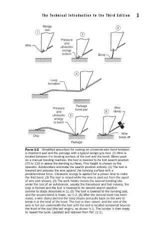
FIGURE 1-2 Simplifi ed procedure for making an ultrasonic-wire bond between
a chip-bond pad and the package with a typical wedge-type tool. (1) Wire is
located between the bonding surface of the tool and the bond. When used
on a manual bonding machine, the tool is lowered to its fi rst search position
(75 to 125 m above the bonding surface). This height is chosen by the
operator. Autobonders eliminate the search position entirely. (2) The tool is
lowered and presses the wire against the bonding surface with a
predetermined force. Ultrasonic energy is applied for a preset time to make
the fi rst bond. (3) The tool is raised while the wire is paid out from the spool
of wire (not shown). (4) The work holder moves the second bonding site
under the tool (if an autobonder, usually the transducer and tool moves), the
loop is formed and the tool is lowered to its second search position
(similar to steps described in 1). (5) The tool is lowered to the bonding pad,
and the second bond is made, as in 2. (6) After the second bond has been
made, a wire clamp (behind the tool) closes and pulls back on the wire to
break it at the heel of the bond. The tool is then raised, and the end of the
wire is fed out underneath the tool until the end is located somewhat beyond
the front of the tool (the tail length), as shown in 1. The bonder is then ready
to repeat the cycle. Updated and redrawn from Ref. [1-2].