
Page 26 - Wire Bonding in Microelectronics
P. 26
The Technical Intr oduction to the Thir d Edition 5
Wedge
Wire
US
energy
Bond pad
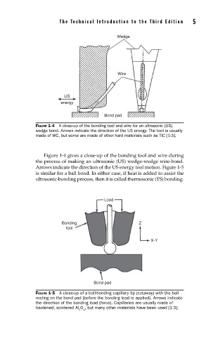
FIGURE 1-4 A close-up of the bonding tool and wire for an ultrasonic (US)
wedge bond. Arrows indicate the direction of the US energy. The tool is usually
made of WC, but some are made of other hard materials such as TiC [1-3].
Figure 1-4 gives a close-up of the bonding tool and wire during
the process of making an ultrasonic (US) wedge-wedge wire-bond.
Arrows indicate the direction of the US energy tool motion. Figure 1-5
is similar for a ball bond. In either case, if heat is added to assist the
ultrasonic-bonding process, then it is called thermosonic (TS) bonding.
Load
Bonding Z
tool
X-Y
Bond pad
FIGURE 1-5 A close-up of a ball-bonding capillary tip (cutaway) with the ball
resting on the bond pad (before the bonding load is applied). Arrows indicate
the direction of the bonding load (force). Capillaries are usually made of
hardened, scintered Al O , but many other materials have been used [1-3].
2 3