
Page 23 - Wire Bonding in Microelectronics
P. 23
2 Cha pte r O n e
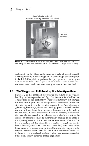
World’s first wire bond!
Note the manually attached wire bonds
The first
wire bond
FIGURE 1-1 Replica of the fi rst transistor, Bell Labs, December 23, 1947,
indicating the fi rst wire interconnection. (Courtesy Bell-Labs/Lucent, 1947.)
A discussion of the differences between various bonding systems with
a table comparing the advantages and disadvantages of each is given
in Table 2-1, Chap. 2, to help choose the appropriate wire bonding, as
well as alternative technologies. Tab, and Beam Leads, which were
once considered leading edge technologies, have almost vanished.
1.1 The Wedge- and Ball-Bonding Machine Operations
Figure 1-2 is the simplified step-by-step procedure of the wedge-
bonding machine operation and Fig. 1-3 is the same for a ball bonder.
The captions are self-explanatory. These procedures have not changed
for more than 30 years, and new diagrams are unnecessary. Some Web
sites give animations of the bonding process, http://www.kns.com/
_flash/cap_bonding_cycle.swf (see Bibliography). Autoball bonders
are several times faster than autowedge bonders, since after making
the ball bond, the wire can be moved, with the capillary, in any direc-
tion to make the second bond; whereas, for wedge bonds, either the
device (or transducer) must be mechanically oriented in an approxi-
mately straight-line direction between the two bonds before the first
bond is made. If not, the thinned heel of the first wedge bond may be
bent sideways (stressed and weakened or cracked) as the wire moves
toward an angled second-bond position. Currently, wire-looping meth-
ods can bend the wire in a smooth radius as it proceeds from the first
to the second bond, and such wedge-bonding rates increase somewhat,
but it seems to have achieved limited application.