
Page 62 - Wire Bonding in Microelectronics
P. 62
Ultrasonic Bonding Systems and Technologies 41
W g
Electrode
Force
(+) (–) Pt wire
Bonding pad
W e Al O 3
2
Substrate
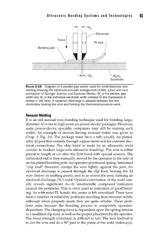
FIGURE 2-19 Diagram of a parallel gap welder used for small-diameter wire
welding showing the electrode-wire-pad arrangement [2-68]. (Used with kind
permission of Springer Science and Business Media.) W is the parallel gap
g
width and W is the individual electrode width (related to the impression it
e
leaves in the wire). A capacitor discharge is passed between the two
electrodes heating the wire and forming the thermocompression weld.
Tweezer Welding
It is an old manual wire-bonding technique used for bonding large-
diameter Al wires to high posts on power-device packages. However,
some power-device specialty companies may still be making such
welds. An example of devices having tweezer welds was given in
Chap. 4, Fig. 4-6. The package must have a tall, usually Au-plated,
alloy 42 post that extends through a glass-metal seal for external elec-
trical connections. The chip bond is made by an ultrasonic weld
(similar to modern large-wire ultrasonic bonding). The wire is either
precut to length or cut after the first bond with special scissors. The
unbonded end is then manually moved by the operator to the side of
an Au-plated bonding post. An operator-positioned spring- tensioned
“clip lead” (tweezer) clamps the wire tightly against the post. An
electrical discharge is passed through the clip lead, heating the Al
wire (below its melting point), and to an extent the post, forming an
electrical discharge (TC) weld. Optical examination of the weld usu-
ally reveals significant Au-Al intermetallic compound formation
around the perimeter. This is often used as indication of good bond-
ing. As with most TC bonds, the center is left unwelded. There have
been a number of reliability problems resulting from tweezer welds,
although when properly made they are quite reliable. These prob-
lems arise because the bonding process is completely operator-
dependent. The clamping force is dependent upon the spring tension
in a modified clip-lead, as well as the proper placement by the operator.
The bond strength (interface) is difficult to test. The best method is
to cut the wire and do a 90° peel in the plane of the weld (sideways).