
Page 86 - Wire Bonding in Microelectronics
P. 86
Bonding W ir e Metallur gy and Characteristics 65
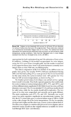
Wire deflection × 2.5 µm (10 –4 in) 10 Al, 1% Mg
12
Al, 1% Cu
8
Al, 1% Si
6
4
2
Measured wire deflection in a 2N2222 transistor operating in a
one minute on - one minute off mode and dissipating 500 mW
2 4 8 12 20 28 36 44
Cycles to failure × 10 3
FIGURE 3-8 Fatigue curves (basically S-N curves) for different 25 µm diameter
for various Al alloy wires that were US wedge-bonded. These data were obtained
by a mechanical accelerated fatigue test on the wires. The dashed bar below
represents the measured wire defl ection that occurred in an actual device under
temperature cycling conditions. Note that the Mg-doped wire is more fatigue
resistant than the Cu-or Si-doped wires [3-15]. (© IEEE .)
appropriate for both understanding and life estimates of bare wires.
In addition, Uebbing [3-16] studied encapsulated Au wire fatigue,
using the S-N curve from wrought gold, and the reader is referred
to his paper for those data. Some wire manufacturers currently have
fatigue data on their Web site, see Bibliography.
One direct comparison of the S-N lifetime of Au (ribbon wire, no
purity data given, but usually 99.99%) between mechanical flexing
(MF) and thermal cycling (T-Cy) were given [3-18]. It was found that
for the same strain, the cycles-to-failure were ∼60% greater for T-Cy
than for MF (at room temperature), as shown in Fig. 3-7.
The broadest general study of wire fatigue was carried out by a group
from Cornell University. They built a special apparatus that could study
the cycles to failure at various temperatures (20°C, 75°C, and 125°C), and
at three different strain amplitudes [3-20]. Both Al and Au wires, at 25 µm
diameter, were used. The Al was standard 1% Si and those results should
be valid today, while the Au results should still be indicative. The two
types of Au wire were unspecified, and currently can be quite different.
The strain amplitudes were 0.7%, 5%, and 10%. Normally one would
expect low-strain repetitive amplitudes in microelectronic systems. For
this, the (0.7%) strain data, gave a cycles-to-failure range of 1000 to 10,000
cycles, with a longer life at the lower temperatures. For the Au samples,
one type had a higher and the other type, a lower, cycles to failure than Al.
The data is too complex to combine and plot in one or two figures, and an
interested reader should use the original reference (available for down-
load through IEEE Xplor. and libraries).