
Page 172 - Mechanical Behavior of Materials
P. 172
Section 4.9 Bending and Torsion Tests 173
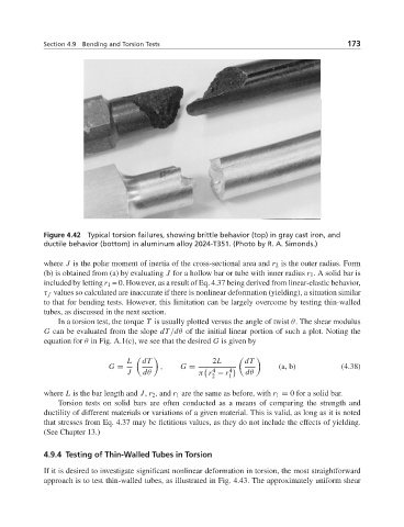
Figure 4.42 Typical torsion failures, showing brittle behavior (top) in gray cast iron, and
ductile behavior (bottom) in aluminum alloy 2024-T351. (Photo by R. A. Simonds.)
where J is the polar moment of inertia of the cross-sectional area and r 2 is the outer radius. Form
(b) is obtained from (a) by evaluating J for a hollow bar or tube with inner radius r 1 . A solid bar is
included by letting r 1 = 0. However, as a result of Eq. 4.37 being derived from linear-elastic behavior,
τ f values so calculated are inaccurate if there is nonlinear deformation (yielding), a situation similar
to that for bending tests. However, this limitation can be largely overcome by testing thin-walled
tubes, as discussed in the next section.
In a torsion test, the torque T is usually plotted versus the angle of twist θ. The shear modulus
G can be evaluated from the slope dT/dθ of the initial linear portion of such a plot. Noting the
equation for θ in Fig. A.1(c), we see that the desired G is given by
L dT 2L dT
G = , G = 4 4 (a, b) (4.38)
J dθ π r − r dθ
2 1
where L is the bar length and J, r 2 , and r 1 are the same as before, with r 1 = 0 for a solid bar.
Torsion tests on solid bars are often conducted as a means of comparing the strength and
ductility of different materials or variations of a given material. This is valid, as long as it is noted
that stresses from Eq. 4.37 may be fictitious values, as they do not include the effects of yielding.
(See Chapter 13.)
4.9.4 Testing of Thin-Walled Tubes in Torsion
If it is desired to investigate significant nonlinear deformation in torsion, the most straightforward
approach is to test thin-walled tubes, as illustrated in Fig. 4.43. The approximately uniform shear