
Page 173 - Mechanical Behavior of Materials
P. 173
174 Chapter 4 Mechanical Testing: Tension Test and Other Basic Tests
r
r 2
1
θ
τ avg r s
T
γ
L
t r avg
(a) (b) (c)
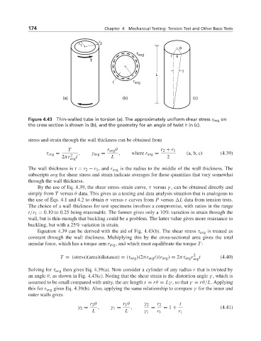
Figure 4.43 Thin-walled tube in torsion (a). The approximately uniform shear stress τ avg on
the cross section is shown in (b), and the geometry for an angle of twist θ in (c).
stress and strain through the wall thickness can be obtained from
T r avg θ r 2 + r 1
τ avg = , γ avg = , where r avg = (a, b, c) (4.39)
2
2πr avg t L 2
The wall thickness is t = r 2 − r 1 , and r avg is the radius to the middle of the wall thickness. The
subscripts avg for shear stress and strain indicate averages for these quantities that vary somewhat
through the wall thickness.
By the use of Eq. 4.39, the shear stress–strain curve, τ versus γ , can be obtained directly and
simply from T versus θ data. This gives us a testing and data analysis situation that is analogous to
the use of Eqs. 4.1 and 4.2 to obtain σ versus ε curves from P versus L data from tension tests.
The choice of a wall thickness for test specimens involves a compromise, with ratios in the range
t/r 1 = 0.10 to 0.25 being reasonable. The former gives only a 10% variation in strain through the
wall, but is thin enough that buckling could be a problem. The latter value gives more resistance to
buckling, but with a 25% variation in strain.
Equation 4.39 can be derived with the aid of Fig. 4.43(b). The shear stress τ avg is treated as
constant through the wall thickness. Multiplying this by the cross-sectional area gives the total
annular force, which has a torque arm r avg , and which must equilibrate the torque T :
T = (stress)(area)(distance) = (τ avg )(2πr avg t)(r avg ) = 2πτ avg r 2 t (4.40)
avg
Solving for τ avg then gives Eq. 4.39(a). Now consider a cylinder of any radius r that is twisted by
an angle θ, as shown in Fig. 4.43(c). Noting that the shear strain is the distortion angle γ , which is
assumed to be small compared with unity, the arc length s = rθ = Lγ , so that γ = rθ/L. Applying
this for r avg gives Eq. 4.39(b). Also, applying the same relationship to compare γ for the inner and
outer walls gives
r 2 θ r 1 θ γ 2 r 2 t
γ 2 = , γ 1 = , = = 1 + (4.41)
L L γ 1 r 1 r 1