
Page 142 - Petroleum Production Engineering, A Computer-Assisted Approach
P. 142
Guo, Boyun / Computer Assited Petroleum Production Engg 0750682701_chap11 Final Proof page 137 3.1.2007 8:54pm Compositor Name: SJoearun
TRANSPORTATION SYSTEMS 11/137
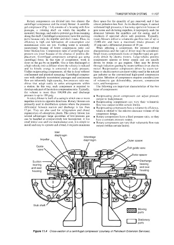
Rotary compressors are divided into two classes: the floor space for the quantity of gas removed, and it has
centrifugal compressor and the rotary blower. A centrifu- almost pulsation-less flow. As its disadvantages, it cannot
gal compressor (Fig. 11.4) consists of a housing with flow withstand high pressures, it has noisy operation because of
passages, a rotating shaft on which the impeller is gear noise and clattering impellers, it improperly seals the
mounted, bearings, and seals to prevent gas from escaping clearance between the impellers and the casing, and it
along the shaft. Centrifugal compressors have few moving overheats if operated above safe pressures. Typically,
parts because only the impeller and shaft rotate. Thus, its rotary blowers deliver a volumetric gas flow rate of up to
efficiency is high and lubrication oil consumption and 17,000 cfm and have a maximum intake pressure of
maintenance costs are low. Cooling water is normally 10 psig and a differential pressure of 10 psi.
unnecessary because of lower compression ratio and When selecting a compressor, the pressure–volume
lower friction loss. Compression rates of centrifugal com- characteristics and the type of driver must be considered.
pressors are lower because of the absence of positive dis- Small rotary compressors (vane or impeller type) are gen-
placement. Centrifugal compressors compress gas using erally driven by electric motors. Large-volume positive
centrifugal force. In this type of compressor, work is compressors operate at lower speeds and are usually
done on the gas by an impeller. Gas is then discharged at driven by steam or gas engines. They may be driven
a high velocity into a diffuser where the velocity is reduced through reduction gearing by steam turbines or an electric
and its kinetic energy is converted to static pressure. motor. Reciprocation compressors driven by steam tur-
Unlike reciprocating compressors, all this is done without bines or electric motors are most widely used in the natural
confinement and physical squeezing. Centrifugal compres- gas industry as the conventional high-speed compression
sors with relatively unrestricted passages and continuous machine. Selection of compressors requires considerations
flow are inherently high-capacity, low-pressure ratio ma- of volumetric gas deliverability, pressure, compression
chines that adapt easily to series arrangements within ratio, and horsepower.
a station. In this way, each compressor is required to The following are important characteristics of the two
develop only part ofthe station compression ratio. Typically, types of compressors:
the volume is more than 100,000 cfm and discharge
pressure is up to 100 psig. . Reciprocating piston compressors can adjust pressure
A rotary blower is built of a casing in which one or more output to backpressure.
impellers rotate in opposite directions. Rotary blowers are . Reciprocating compressors can vary their volumetric
primarily used in distribution systems where the pressure flow-rate output (within certain limits).
differential between suction and discharge is less than . Reciprocating compressors have a volumetric efficiency,
15 psi. They are also used for refrigeration and closed which is related to the relative clearance volume of the
regeneration of adsorption plants. The rotary blower has compressor design.
several advantages: large quantities of low-pressure gas . Rotary compressors have a fixed pressure ratio, so they
can be handled at comparatively low horsepower, it has have a constant pressure output.
small initial cost and low maintenance cost, it is simple to . Rotary compressors can vary their volumetric flow-rate
install and easy to operate and attend, it requires minimum output (within certain limits).
Inlet
diaphragm
Interstage
Impeller diaphragm Outer spacer
Guide Exit guide vane
vane
Rotor spacer
Suction Discharge
bearing bearing
and seal and seal
housing housing
Stub shaft
Moving
parts
Stationary
parts
Figure 11.4 Cross-section of a centrifugal compressor (courtesy of Petroleum Extension Services).