
Page 144 - Petroleum Production Engineering, A Computer-Assisted Approach
P. 144
Guo, Boyun / Computer Assited Petroleum Production Engg 0750682701_chap11 Final Proof page 139 3.1.2007 8:54pm Compositor Name: SJoearun
TRANSPORTATION SYSTEMS 11/139
R 3
W s ¼ (T 2 T 1 ) þ P 2 v 2 P 1 v 1 where Q 1 (ft =sec) is the volumetric flow rate into the
k 1 compressor and Q 2 (ft =sec) would be the compressed
3
2
2
(V V ) volumetric flow rate out of the compressor. Substituting
þ 2 1 : (11:43) Eq. (11.32) and (11.51) into (11.50) yields
2g " k 1 #
And because P s ¼ k P 1 Q 1 P 2 k 1 : (11:52)
(11:44) k 1 P 1
P 1 v 1 ¼ RT 1
and If we use more conventional field terms such as
P 2 v 2 ¼ RT 2 , (11:45) P 1 ¼ p 1 (144) where p 1 is in psia
Eq. (11.43) becomes P 2 ¼ p 2 (144) where p 2 is in psia
R and
W s ¼ (T 2 T 1 ) þ R(T 2 T 1 )
k 1 q 1
Q 1 ¼ where q 1 is in cfm,
2
2
(V V ) 60
þ 2 1 , (11:46)
2g and knowing that 1 horsepower ¼ 550 ft-lb/sec, then Eq.
(11.52) becomes
but rearranging Eq. (11.46) gives " #
k 1
2
2
k T 2 (V V ) k p 1 (144)q 1 p 2 k
W s ¼ RT 1 1 þ 2 1 : HP ¼ 1 ,
k 1 T 1 2g (k 1) 550(60) p 1
Substituting Eq. (11.41) and (11.44) into the above gives which yields
" # " #
2
2
k
k P 2 k 1 (V V ) k 1
W s ¼ P 1 v 1 1 þ 2 1 : (11:47) HP ¼ k p 1 q 1 p 2 k 1 : (11:53)
k 1 P 1 2g (k 1) 229:2 p 1
Neglecting the kinetic energy term, we arrive at If the gas flow rate is given in Q MM (MMscf/day) in a
" #
k
k P 2 k 1 standard base condition at base pressure p b (e.g.,
W s ¼ P 1 v 1 1 , (11:48) 14.7 psia) and base temperature T b (e.g., 520 8R), since
k 1 P 1
p b T 1 Q MM (1,000,000)
where W s is ft-lb/lb, that is, work done per lb. q 1 ¼ p 1 T b (24) , (11:54)
It is convenient to obtain an expression for power under
conditions of steady state gas flow. Substituting Eq. Eq. (11.53) becomes " #
(11.44) into (11.48) yields k k 1 k
" # HP ¼ 181:79p b T 1 Q MM p 2 1 : (11:55)
k P 2 k 1 T b (k 1) p 1
k
W s ¼ RT 1 1 : (11:49)
k 1 P 1
It will beshown later thatthe efficiency ofcompressiondrops
If we multiply both sides of Eq. (11.49) by the weight rate with increased compression ratio p 2 =p 1 . Most field applica-
of flow, w t (lb/sec), through the system, we get tions require multistage compressors (two, three, and some-
" # times four stages) to reduce compression ratio in each stage.
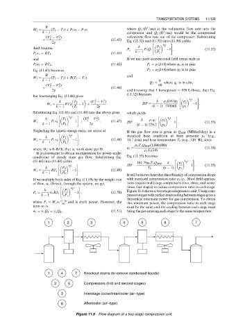
k P 2 k 1 Figure 11.6 shows a two-stage compression unit. Using com-
k
P s ¼ w t RT 1 1 , (11:50)
k 1 P 1 pressorstageswithperfectintercoolingbetweenstagesgivesa
theoretical minimum power for gas compression. To obtain
ft lb
where P s ¼ W s w t sec and is shaft power. However, the this minimum power, the compression ratio in each stage
term w t is must be the same and the cooling between each stage must
w t ¼ g 1 Q 1 ¼ g 2 Q 2 , (11:51) bring the gas entering each stage to the same temperature.
1 2 3 4 5 6 7
1 4 7 Knockout drums (to remove condensed liquids)
2 5 Compressors (first and second stages)
3 Interstage cooler/intercooler (air−type)
6 Aftercooler (air−type)
Figure 11.6 Flow diagram of a two-stage compression unit.