
Page 149 - Petroleum Production Engineering, A Computer-Assisted Approach
P. 149
Guo, Boyun / Computer Assited Petroleum Production Engg 0750682701_chap11 Final Proof page 144 3.1.2007 8:54pm Compositor Name: SJoearun
11/144 EQUIPMENT DESIGN AND SELECTION
rudu ¼ pressure gradient due to acceleration or in a circular pipe. If U.S. field units of ft for diameter, ft/
g c dL kinetic energy change sec for velocity, lb m =ft 3 for density and centipoises
P ¼ pressure, lbf=ft 2 for viscosity are used, the Reynolds number equation
L ¼ pipe length, ft becomes
g ¼ gravitational acceleration, ft=sec 2 Dur
g c ¼ 32:17, ft-lbm=lbf-sec 2 N Re ¼ 1,488 : (11:80)
r ¼ density lbm=ft 3 m
u ¼ dip angle from horizontal direction, For a gas with specific gravity g g and viscosity m g
degrees (cp) flowing in a pipe with an inner diameter D (in.)
f M ¼ Darcy–Wiesbach (Moody) friction factor at flow rate q (Mcfd) measured at base conditions of T b
u ¼ flow velocity, ft/sec (8R) and p b (psia), the Reynolds number can be expressed
D ¼ pipe inner diameter, ft as
The elevation component is pipe-angle dependent. It is N Re ¼ 711p b qg g : (11:81)
zero for horizontal flow. The friction loss component T b Dm g
applies to any type of flow at any pipe angle and causes
a pressure drop in the direction of flow. The acceleration The Reynolds number usually takes values greater than
component causes a pressure drop in the direction of 10,000 in gas pipelines. As T b is 520 8R and p b varies only
velocity increase in any flow condition in which velocity from 14.4 to 15.025 psia in the United States, the value of
711pb/Tb varies between 19.69 and 20.54. For all practical
changes occurs. It is zero for constant-area, incompressible purposes, the Reynolds number for natural gas flow prob-
flow. This term is normally negligible for both oil and gas lems may be expressed as
pipelines.
The friction factor f M in Eq. (11.78) can be determined N Re ¼ 20qg g , (11:82)
based on flow regimes, that is, laminar flow or turbulent m g d
flow. Reynolds number (N Re ) is used as a parameter
to distinguish between laminar and turbulent fluid flow. where
Reynolds number is defined as the ratio of fluid momen- q ¼ gas flow rate at 60 8F and 14.73 psia, Mcfd
tum force to viscous shear force. The Reynolds g g ¼ gas-specific gravity (air ¼ 1)
number can be expressed as a dimensionless group defined m g ¼ gas viscosity at in-situ temperature and pressure,
as cp
Dur d ¼ pipe diameter, in.
N Re ¼ , (11:79)
m The coefficient 20 becomes 0.48 if q is in scfh.
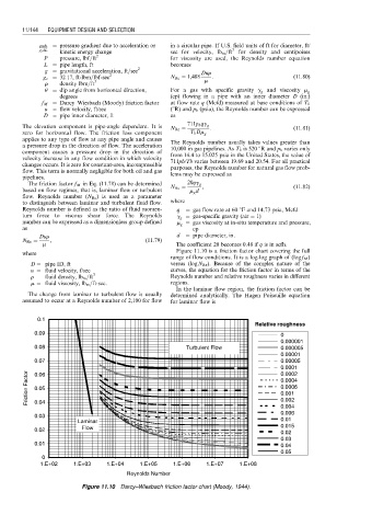
Figure 11.10 is a friction factor chart covering the full
where
range of flow conditions. It is a log-log graph of (log f M )
D ¼ pipe ID, ft versus (log N Re ). Because of the complex nature of the
u ¼ fluid velocity, f/sec curves, the equation for the friction factor in terms of the
3
r ¼ fluid density, lb m =ft Reynolds number and relative roughness varies in different
m ¼ fluid viscosity, lb m =ft-sec. regions.
In the laminar flow region, the friction factor can be
The change from laminar to turbulent flow is usually determined analytically. The Hagen–Poiseuille equation
assumed to occur at a Reynolds number of 2,100 for flow for laminar flow is
0.1
Relative roughness
0.09 0
0.000001
0.08 Turbulent Flow 0.000005
0.00001
0.07 0.00005
0.0001
Friction Factor 0.05 0.0004
0.0002
0.06
0.0006
0.001
0.002
0.04
0.004
0.006
0.03
Laminar 0.01
0.02 Flow 0.015
0.02
0.03
0.01 0.04
0.05
0
1.E+02 1.E+03 1.E+04 1.E+05 1.E+06 1.E+07 1.E+08
Reynolds Number
Figure 11.10 Darcy–Wiesbach friction factor chart (Moody, 1944).