
Page 154 - Petroleum Production Engineering, A Computer-Assisted Approach
P. 154
Guo, Boyun / Computer Assited Petroleum Production Engg 0750682701_chap11 Final Proof page 149 3.1.2007 8:54pm Compositor Name: SJoearun
TRANSPORTATION SYSTEMS 11/149
. Electric resistance welded (ERW) Step 6: Check for handling practice, that is, pipeline han-
. Spiral weld. dling is difficult for D/t larger than 50; welding of
wall thickness less than 0.3 in (7.6 mm) requires
Except in specific cases, only seamless or SAW pipes are to special provisions.
be used, with seamless being the preference for diameters
of 12 in. or less. If ERW pipe is used, special inspection Note that in certain cases, it may be desirable to order a
provisions such as full-body ultrasonic testing are re- nonstandard wall. This can be done for large orders.
quired. Spiral weld pipe is very unusual for oil/gas pipe- Pipelines are sized on the basis of the maximum
lines and should be used only for low-pressure water or expected stresses in the pipeline under operating condi-
outfall lines.
tions. The stress calculation methods are different for
thin-wall and thick-wall pipes. A thin-wall pipe is defined
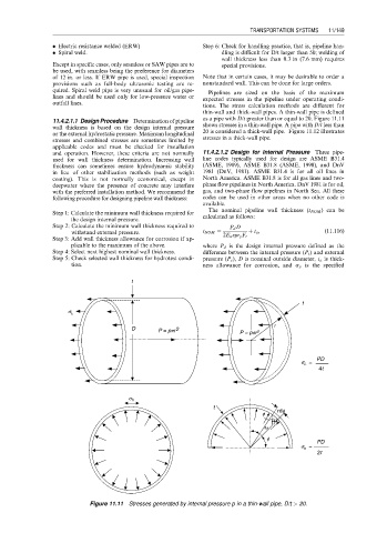
as a pipe with D/t greater than or equal to 20. Figure 11.11
11.4.2.1.1 Design Procedure Determination of pipeline
wall thickness is based on the design internal pressure shows stresses in a thin-wall pipe. A pipe with D/t less than
or the external hydrostatic pressure. Maximum longitudinal 20 is considered a thick-wall pipe. Figure 11.12 illustrates
stresses and combined stresses are sometimes limited by stresses in a thick-wall pipe.
applicable codes and must be checked for installation
and operation. However, these criteria are not normally 11.4.2.1.2 Design for Internal Pressure Three pipe-
used for wall thickness determination. Increasing wall line codes typically used for design are ASME B31.4
thickness can sometimes ensure hydrodynamic stability (ASME, 1989), ASME B31.8 (ASME, 1990), and DnV
in lieu of other stabilization methods (such as weight 1981 (DnV, 1981). ASME B31.4 is for all oil lines in
coating). This is not normally economical, except in North America. ASME B31.8 is for all gas lines and two-
deepwater where the presence of concrete may interfere phase flow pipelines in North America. DnV 1981 is for oil,
with the preferred installation method. We recommend the gas, and two-phase flow pipelines in North Sea. All these
following procedure for designing pipeline wall thickness: codes can be used in other areas when no other code is
available.
The nominal pipeline wall thickness (t NOM ) can be
Step 1: Calculate the minimum wall thickness required for
calculated as follows:
the design internal pressure.
Step 2: Calculate the minimum wall thickness required to P d D
withstand external pressure. t NOM ¼ þ t a , (11:116)
2E w hs y F t
Step 3: Add wall thickness allowance for corrosion if ap-
plicable to the maximum of the above. where P d is the design internal pressure defined as the
Step 4: Select next highest nominal wall thickness. difference between the internal pressure (P i ) and external
Step 5: Check selected wall thickness for hydrotest condi- pressure (P e ), D is nominal outside diameter, t a is thick-
tion. ness allowance for corrosion, and s y is the specified
t
t
s L
r
D P = ppr 2 P = ppr 2
PD
s L =
4t
s h
t rdf
f
dφ df
f PD
s h =
2t
Figure 11.11 Stresses generated by internal pressure p in a thin-wall pipe, D/t > 20.