
Page 155 - Petroleum Production Engineering, A Computer-Assisted Approach
P. 155
Guo, Boyun / Computer Assited Petroleum Production Engg 0750682701_chap11 Final Proof page 150 3.1.2007 8:54pm Compositor Name: SJoearun
11/150 EQUIPMENT DESIGN AND SELECTION
Table 11.2 Design and Hydrostatic Pressure Definitions and Usage Factors for Oil Lines
Parameter ASME B31.4, 1989 Edition Dnv (Veritas, 1981)
Design internal pressure P a d P i P e [401:2:2] P i P e [4.2.2.2]
Usage factor h 0.72 [402.3.1(a)] 0.72 [4.2.2.1]
b
Hydrotest pressure P h 1:25 P [437.4.1(a)] 1:25P d [8.8.4.3]
i
a
Credit can be taken for external pressure for gathering lines or flowlines when the MAOP (P i ) is applied at the wellhead
or at the seabed. For export lines, when P i is applied on a platform deck, the head fluid shall be added to P i for the
pipeline section on the seabed.
b
If hoop stress exceeds 90% of yield stress based on nominal wall thickness, special care should be taken to prevent
overstrain of the pipe.
minimum yield strength. Equation (11.116) is valid for any external pressure criteria. As a rule of thumb, or unless
consistent units. qualified thereafter, it is recommended to use propagation
Most codes allow credit for external pressure. This credit criterion for pipeline diameters under 16-in. and collapse
should be used whenever possible, although care should be criterion for pipeline diameters more than or equal to 16-in.
exercised for oil export lines to account for head of fluid and
Propagation Criterion: The propagation criterion is more
for lines that traverse from deep to shallow water.
conservative and should be used where optimization of the
ASME B31.4 and DnV 1981 define P i as the maximum
wall thickness is not required or for pipeline installation
allowable operating pressure (MAOP) under normal condi-
tions, indicating that surge pressures up to 110% MAOP is methods not compatible with the use of buckle arrestors
acceptable. In some cases, P i is defined as wellhead shut-in such as reel and tow methods. It is generally economical to
pressure (WSIP) for flowlines or specified by the operators. design for propagation pressure for diameters less than
In Eq. (11.116), the weld efficiency factor (E w ) is 1.0 for 16-in. For greater diameters, the wall thickness penalty is
seamless, ERW, and DSAW pipes. The temperature de- too high. When a pipeline is designed based on the collapse
rating factor (F t ) is equal to 1.0 for temperatures under criterion, buckle arrestors are recommended. The external
250 8F. The usage factor (h) is defined in Tables 11.2 and pressure criterion should be based on nominal wall thick-
11.3 for oil and gas lines, respectively. ness, as the safety factors included below account for wall
The underthickness due to manufacturing tolerance is variations.
taken into account in the design factor. There is no need to Although a large number of empirical relationships have
add any allowance for fabrication to the wall thickness been published, the recommended formula is the latest
calculated with Eq. (11.116). given by AGA.PRC (AGA, 1990):
2:46
t NOM
11.4.2.1.3 Design for External Pressure Different P P ¼ 33S y , (11:117)
practices can be found in the industry using different D
s r + ds r dr
P O
m1 dr
2
s h
m1
n1
n1 m
m dr 2
n sr n s h
r
df
P
b
a
s = − P O
ra
s = −P
rb
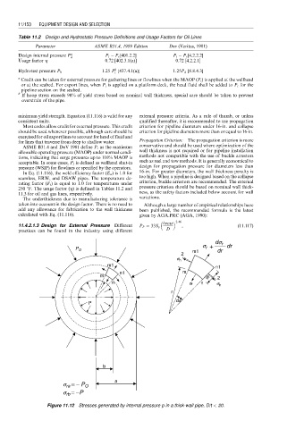
Figure 11.12 Stresses generated by internal pressure p in a thick-wall pipe, D/t < 20.