
Page 156 - Petroleum Production Engineering, A Computer-Assisted Approach
P. 156
Guo, Boyun / Computer Assited Petroleum Production Engg 0750682701_chap11 Final Proof page 151 3.1.2007 8:54pm Compositor Name: SJoearun
TRANSPORTATION SYSTEMS 11/151
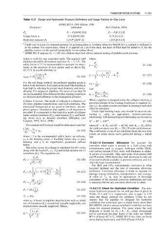
Table 11.3 Design and Hydrostatic Pressure Definitions and Usage Factors for Gas Lines
ASME B31.8, 1989 Edition, 1990
Parameter Addendum DnV (Veritas, 1981)
P a P i P e [A842.221] P i P e [4.2.2.2]
d
Usage factor h 0.72 [A842.221] 0.72 [4.2.2.1]
b
1:25 P [A847.2] 1:25P d [8.8.4.3]
Hydrotest pressure P h
i
a
Credit can be taken for external pressure for gathering lines or flowlines when the MAOP (P i ) is applied at wellhead or
at the seabed. For export lines, when P i is applied on a platform deck, the head of fluid shall be added to P i for the
pipeline section on the seabed (particularly for two-phase flow).
b
ASME B31.8 imposes P h ¼ 1:4P i for offshore risers but allows onshore testing of prefabricated portions.
which is valid for any consistent units. The nominal wall where
thickness should be determined such that P p > 1:3 P e . The 0
safety factor of 1.3 is recommended to account for uncer- p ¼ P y , (11:126)
tainty in the envelope of data points used to derive Eq. P el
(11.117). It can be rewritten as s ffiffiffiffiffiffiffiffiffiffiffiffiffiffiffiffiffiffiffiffiffiffiffiffiffiffiffi
1 D 2 D
2:46
1:3P P f p ¼ 1 þ d o d o , (11:127)
t NOM $ D : (11:118) t t
33S y
For the reel barge method, the preferred pipeline grade is « B ¼ t , (11:128)
belowX-60.However, X-65 steel can beusedif the ductility is 2D
kept high by selecting the proper steel chemistry and micro- and
alloying. For deepwater pipelines, D/t ratios of less than 30
D max D min
are recommended. It has been noted that bending loads have d o ¼ : (11:129)
no demonstrated influence on the propagation pressure. D max þ D min
When a pipeline is designed using the collapse criterion, a
Collapse Criterion: The mode of collapse is a function of
D/t ratio, pipeline imperfections, and load conditions. The good knowledge of the loading conditions is required (T a
theoretical background is not given in this book. An em- and « b ). An upper conservative limit is necessary and must
pirical general formulation that applies to all situations is often be estimated.
provided. It corresponds to the transition mode of collapse Under high bending loads, care should be taken in esti-
under external pressure (P e ), axial tension (T a ), and bend- mating « b using an appropriate moment-curvature
ing strain (s b ), as detailed elsewhere (Murphey and relationship. A Ramberg Osgood relationship can be used as
Langner, 1985; AGA, 1990). K ¼ M þ AM , (11:130)
B
The nominal wall thickness should be determined such that where K ¼ K=K y and M ¼ M=M y with K y ¼ 2S y =ED is
the yield curvature and M y ¼ 2IS y =D is the yield moment.
1:3P P « b
þ # g p , (11:119) The coefficients A and B are calculated from the two data
P C « B
points on stress–strain curve generated during a tensile
where 1.3 is the recommended safety factor on collapse, test.
« B is the bending strain of buckling failure due to pure
bending, and g is an imperfection parameter defined 11.4.2.1.4 Corrosion Allowance To account for
below. corrosion when water is present in a fluid along with
The safety factor on collapse is calculated for D/t ratios contaminants such as oxygen, hydrogen sulfide (H 2 S),
along with the loads (P e , « b , T a ) and initial pipeline out-of and carbon dioxide (CO 2 ), extra wall thickness is added.
roundness (d o ). The equations are A review of standards, rules, and codes of practices (Hill
0 and Warwick, 1986) shows that wall allowance is only one
P el P y
P C ¼ q ffiffiffiffiffiffiffiffiffiffiffiffiffiffiffiffiffiffiffi , (11:120) of several methods available to prevent corrosion, and it is
2
P þ P 0 2 often the least recommended.
el y
For H 2 S and CO 2 contaminants, corrosion is often
2 s ffiffiffiffiffiffiffiffiffiffiffiffiffiffiffiffiffiffiffiffiffiffiffiffiffiffiffiffiffiffiffi 3
2 localized (pitting) and the rate of corrosion allowance
0 4 T a T a 5 , ineffective. Corrosion allowance is made to account for
P ¼ P y 1 0:75 (11:121)
y
T y 2T y damage during fabrication, transportation, and storage.
1
A value of ⁄ 16 in. may be appropriate. A thorough
2E 3 assessment of the internal corrosion mechanism and rate
t
P el ¼ , (11:122) is necessary before any corrosion allowance is taken.
1 n 2 D
t 11.4.2.1.5 Check for Hydrotest Condition The min-
P y ¼ 2S y , (11:123)
D imum hydrotest pressure for oil and gas lines is given in
Tables 11.2 and 11.3, respectively, and is equal to 1.25
T y ¼ AS y , (11:124) times the design pressure for pipelines. Codes do not
where g p is based on pipeline imperfections such as initial require that the pipeline be designed for hydrotest
out-of roundness (d o ), eccentricity (usually neglected), and conditions but sometimes give a tensile hoop stress limit
residual stress (usually neglected). Hence, 90% SMYS, which is always satisfied if credit has not been
v ffiffiffiffiffiffiffiffiffiffiffiffiffiffiffiffi taken for external pressure. For cases where the wall
u 1 þ p 2 thickness is based on P d ¼ P i P e , codes recommend
u
g p ¼ t , (11:125) not to overstrain the pipe. Some of the codes are ASME
2
p f 2 1
p B31.4 (Clause 437.4.1), ASME B31.8 (no limit on hoop
stress during hydrotest), and DnV (Clause 8.8.4.3).