
Page 161 - Petroleum Production Engineering, A Computer-Assisted Approach
P. 161
Guo, Boyun / Computer Assited Petroleum Production Engg 0750682701_chap11 Final Proof page 156 3.1.2007 8:54pm Compositor Name: SJoearun
11/156 EQUIPMENT DESIGN AND SELECTION
30
25
Temperature ( C) 20 0 minute
15
10 minutes
20 minutes
30 minutes
10
Steady flow
5
0
0 2,000 4,000 6,000 8,000 10,000
Distance (M)
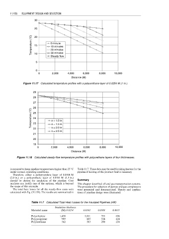
Figure 11.17 Calculated temperature profiles with a polyurethane layer of 0.0254 M (1 in.).
29
28
27
26
Temperature ( C) 25 s = 1.0 in
24
23
s = 2.0 in
22 s = 1.5 in
s = 2.5 in
21
20
19
0 2,000 4,000 6,000 8,000 10,000
Distance (M)
Figure 11.18 Calculated steady-flow temperature profiles with polyurethane layers of four thicknesses.
is required to keep pipeline temperatures higher than 25 8C Table 11.7. These data may be used for sizing heaters for the
under normal operating conditions. pipeline if heating of the product fluid is necessary.
Therefore, either a polypropylene layer of 0.0508 M
(2.0 in.) or a polyurethane layer of 0.0381 M (1.5 in.)
should be chosen for insulation of the pipeline. Cost Summary
analyses can justify one of the options, which is beyond This chapter described oil and gas transportation systems.
the scope of this example. The procedure for selection of pumps and gas compressors
The total heat losses for all the steady-flow cases were were presented and demonstrated. Theory and applica-
calculated with Eq. (11.138). The results are summarized in tions of pipeline design were illustrated.
Table 11.7 Calculated Total Heat Losses for the Insulated Pipelines (kW)
Insulation thickness
Material name (M) 0.0254 0.0381 0.0508 0.0635
Polyethylene 1,430 1,011 781 636
Polypropylene 989 685 524 424
Polyurethane 562 383 290 234