
Page 166 - Petroleum Production Engineering, A Computer-Assisted Approach
P. 166
Guo, Boyun / Computer Assited Petroleum Production Engg 0750682701_chap12 Final Proof page 162 4.1.2007 2:43pm Compositor Name: SJoearun
12/162 ARTIFICIAL LIFT METHODS
12.1 Introduction by means of the walking beam through a pitman arm. The
horse’s head and the hanger cable arrangement is used to
Sucker rod pumping is also referred to as ‘‘beam pump-
ing.’’ It provides mechanical energy to lift oil from bottom ensure that the upward pull on the sucker rod string is
hole to surface. It is efficient, simple, and easy for field vertical at all times (thus, no bending moment is applied to
people to operate. It can pump a well down to very low the stuffing box). The polished rod and stuffing box com-
pressure to maximize oil production rate. It is applicable to bine to maintain a good liquid seal at the surface and, thus,
slim holes, multiple completions, and high-temperature force fluid to flow into the ‘‘T’’ connection just below the
and viscous oils. The system is also easy to change to stuffing box.
other wells with minimum cost. The major disadvantages Conventional pumping units are available in a wide
of beam pumping include excessive friction in crooked/ range of sizes, with stroke lengths varying from 12 to
deviated holes, solid-sensitive problems, low efficiency in almost 200 in. The strokes for any pumping unit type are
gassy wells, limited depth due to rod capacity, and bulky in available in increments (unit size). Within each unit size,
offshore operations. Beam pumping trends include the stroke length can be varied within limits (about six
improved pump-off controllers, better gas separation, gas different lengths being possible). These different lengths
handling pumps, and optimization using surface and are achieved by varying the position of the pitman arm
bottom-hole cards. connection on the crank arm.
Walking beam ratings are expressed in allowable pol-
ished rod loads (PRLs) and vary from approximately
3,000 to 35,000 lb. Counterbalance for conventional
12.2 Pumping System
pumping units is accomplished by placing weights directly
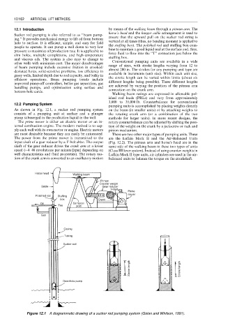
As shown in Fig. 12.1, a sucker rod pumping system on the beam (in smaller units) or by attaching weights to
consists of a pumping unit at surface and a plunger the rotating crank arm (or a combination of the two
pump submerged in the production liquid in the well. methods for larger units). In more recent designs, the
The prime mover is either an electric motor or an in- rotary counterbalance can be adjusted by shifting the posi-
ternal combustion engine. The modern method is to sup- tion of the weight on the crank by a jackscrew or rack and
ply each well with its own motor or engine. Electric motors pinion mechanism.
are most desirable because they can easily be automated. There are two other major types of pumping units. These
The power from the prime mover is transmitted to the are the Lufkin Mark II and the Air-Balanced Units
input shaft of a gear reducer by a V-belt drive. The output (Fig. 12.2). The pitman arm and horse’s head are in the
shaft of the gear reducer drives the crank arm at a lower same side of the walking beam in these two types of units
speed ( 4–40 revolutions per minute [rpm] depending on (Class III lever system). Instead of using counter-weights in
well characteristics and fluid properties). The rotary mo- Lufkin Mark II type units, air cylinders are used in the air-
tion of the crank arm is converted to an oscillatory motion balanced units to balance the torque on the crankshaft.
Horse head
Walking beam
Pitman
Counter weight
Bridle Gear reducer
V-Belt
Prime
mover
Polished rod Stuffing
box Crank
Oil Sampson
Tee post
Gas
Casing
Tubing
Sucker rod
Stroke length Stroke length
Downhole pump
Figure 12.1 A diagrammatic drawing of a sucker rod pumping system (Golan and Whitson, 1991).