
Page 169 - Petroleum Production Engineering, A Computer-Assisted Approach
P. 169
Guo, Boyun / Computer Assited Petroleum Production Engg 0750682701_chap12 Final Proof page 165 4.1.2007 2:43pm Compositor Name: SJoearun
SUCKER ROD PUMPING 12/165
passing through the open SV). The fluid continues to fill conventional pumping units. Parameters are defined in
the volume above the SV until the plunger reaches the top Fig. 12.6.
of its stroke.
There are two basic types of plunger pumps: tubing Air-Balanced Pumping Unit. For this type of unit, the
pump and rod pump (Fig. 12.4). For the tubing pump, maximum acceleration occurs at the top of the stroke
the working barrel or liner (with the SV) is made up (i.e., (the acceleration at the bottom of the stroke is less than
attached) to the bottom of the production tubing string simple harmonic motion). Thus, a lower maximum stress is
and must be run into the well with the tubing. The plunger set up in the rod system during transfer of the fluid load to
(with the TV) is run into the well (inside the tubing) on the rods.
the sucker rod string. Once the plunger is seated in the
working barrel, pumping can be initiated. A rod pump The following analyses of polished rod motion apply to
(both working barrel and plunger) is run into the well on conventional units. Figure 12.7 illustrates an approximate
the sucker rod string and is seated on a wedged type motion of the connection point between pitman arm and
seat that is fixed to the bottom joint of the production walking beam.
5
5
tubing. Plunger diameters vary from ⁄ 8 to 4 ⁄ 8 in. Plunger If x denotes the distance of B below its top position C
2
2
area varies from 0:307 in: to 17:721 in: . and is measured from the instant at which the crank arm
and pitman arm are in the vertical position with the crank
arm vertically upward, the law of cosine gives
2
2
2
12.3 Polished Rod Motion (AB) ¼ (OA) þ (OB) 2(OA)(OB) cos AOB,
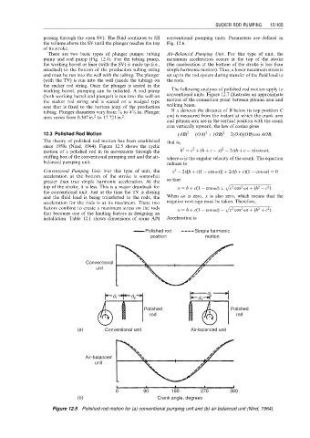
The theory of polished rod motion has been established that is,
since 1950s (Nind, 1964). Figure 12.5 shows the cyclic 2 2 2
motion of a polished rod in its movements through the h ¼ c þ (h þ c x) 2c(h þ c x) cos vt,
stuffing box of the conventional pumping unit and the air- where v is the angular velocity of the crank. The equation
balanced pumping unit. reduces to
2
Conventional Pumping Unit. For this type of unit, the x 2x[h þ c(1 cos vt)] þ 2c(h þ c)(1 cos vt) ¼ 0
acceleration at the bottom of the stroke is somewhat
greater than true simple harmonic acceleration. At the so that p ffiffiffiffiffiffiffiffiffiffiffiffiffiffiffiffiffiffiffiffiffiffiffiffiffiffiffiffiffiffiffiffiffiffiffiffiffiffiffiffiffiffiffi
top of the stroke, it is less. This is a major drawback for x ¼ h þ c(1 cos vt) c cos vt þ (h c ):
2
2
2
2
the conventional unit. Just at the time the TV is closing
and the fluid load is being transferred to the rods, the When vt is zero, x is also zero, which means that the
acceleration for the rods is at its maximum. These two negative root sign must be taken. Therefore,
factors combine to create a maximum stress on the rods x ¼ h þ c(1 cos vt) p ffiffiffiffiffiffiffiffiffiffiffiffiffiffiffiffiffiffiffiffiffiffiffiffiffiffiffiffiffiffiffiffiffiffiffiffiffiffiffiffiffiffiffi
2
2
2
2
c cos vt þ (h þ c ):
that becomes one of the limiting factors in designing an
installation. Table 12.1 shows dimensions of some API Acceleration is
Polished rod Simple harmonic
position motion
Conventional
unit
d 2
d 1 d 2 d 1
Polished Polished
rod rod
(a) Conventional unit Air-balanced unit
Air-balanced
unit
0 90 180 270 360
(b) Crank angle, degrees
Figure 12.5 Polished rod motion for (a) conventional pumping unit and (b) air-balanced unit (Nind, 1964).