
Page 168 - Petroleum Production Engineering, A Computer-Assisted Approach
P. 168
Guo, Boyun / Computer Assited Petroleum Production Engg 0750682701_chap12 Final Proof page 164 4.1.2007 2:43pm Compositor Name: SJoearun
12/164 ARTIFICIAL LIFT METHODS
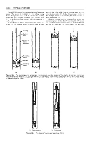
Figure 12.3 illustrates the working principle of a plunger through the valve, which lets the plunger move to a po-
pump. The pump is installed in the tubing string sition just above the SV. During this downward motion of
below the dynamic liquid level. It consists of a working the plunger, the SV is closed; thus, the fluid is forced to
barrel and liner, standing valve (SV), and traveling valve pass through the TV.
(TV) at the bottom of the plunger, which is connected to When the plunger is at the bottom of the stroke and
sucker rods. starts an upward stroke, the TV closes and the SV opens.
As the plunger is moved downward by the sucker rod As upward motion continues, the fluid in the well below
string, the TV is open, which allows the fluid to pass the SV is drawn into the volume above the SV (fluid
Tubing
Sucker
rods
Working
barrel
and liner
Traveling
valve
plunger
Standing
valve
(a) (b) (c) (d)
Figure 12.3 The pumping cycle: (a) plunger moving down, near the bottom of the stroke; (b) plunger moving up,
near the bottom of the stroke; (c) plunger moving up, near the top of the stroke; (d) plunger moving down, near the top
of the stroke (Nind, 1964).
(a) Tubing pump (b) Rod pump
Figure 12.4 Two types of plunger pumps (Nind, 1964).