
Page 16 - Petroleum Production Engineering, A Computer-Assisted Approach
P. 16
Guo, Boyun / Computer Assited Petroleum Production Engg 0750682701_chap01 Final Proof page 4 4.1.2007 6:12pm Compositor Name: SJoearun
1/4 PETROLEUM PRODUCTION ENGINEERING FUNDAMENTALS
1.1 Introduction no more gas at the given temperature. Single (liquid)-phase
flow prevails in an undersaturated oil reservoir, whereas
The role of a production engineer is to maximize oil and
gas production in a cost-effective manner. Familiarization two-phase (liquid oil and free gas) flow exists in a sat-
and understanding of oil and gas production systems are urated oil reservoir.
essential to the engineers. This chapter provides graduat- Wells in the same reservoir can fall into categories of
ing production engineers with some basic knowledge oil, condensate, and gas wells depending on the producing
about production systems. More engineering principles gas–oilratio(GOR).GaswellsarewellswithproducingGOR
are discussed in the later chapters. being greater than 100,000 scf/stb; condensate wells are those
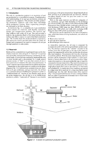
As shown in Fig. 1.1, a complete oil or gas production with producing GOR being less than 100,000 scf/stb but
system consists of a reservoir, well, flowline, separators, greater than 5,000 scf/stb; and wells with producing GOR
pumps, and transportation pipelines. The reservoir sup- being less than 5,000 scf/stb are classified as oil wells.
plies wellbore with crude oil or gas. The well provides a Oil reservoirs can be classified on the basis of boundary
path for the production fluid to flow from bottom hole to type, which determines driving mechanism, and which are
surface and offers a means to control the fluid production as follows:
rate. The flowline leads the produced fluid to separators. . Water-drive reservoir
The separators remove gas and water from the crude oil. . Gas-cap drive reservoir
Pumps and compressors are used to transport oil and gas . Dissolved-gas drive reservoir
through pipelines to sales points.
In water-drive reservoirs, the oil zone is connected by
a continuous path to the surface groundwater system (aqui-
fer). The pressure caused by the ‘‘column’’ of water to the
1.2 Reservoir
surface forces the oil (and gas) to the top of the reservoir
Hydrocarbon accumulations in geological traps can be clas- against the impermeable barrier that restricts the oil and gas
sified as reservoir, field, and pool. A ‘‘reservoir’’ is a porous (the trap boundary). This pressure will force the oil and gas
and permeable underground formation containing an indi- toward the wellbore. With the same oil production, reservoir
vidual bank of hydrocarbons confined by impermeable rock pressure will be maintained longer (relative to other mech-
or water barriers and is characterized by a single natural anisms of drive) when there is an active water drive. Edge-
pressure system. A ‘‘field’’ is an area that consists of one or water drive reservoir is the most preferable type of reservoir
more reservoirs all related to the same structural feature. A compared to bottom-water drive. The reservoir pressure can
‘‘pool’’ contains one or more reservoirs in isolated structures. remain at its initial value above bubble-point pressure so that
Depending on the initial reservoir condition in the phase single-phase liquid flow exists in the reservoir for maximum
diagram (Fig. 1.2), hydrocarbon accumulations are classi- well productivity. A steady-state flow condition can prevail
fied as oil, gas condensate, and gas reservoirs. An oil that in a edge-water drive reservoir for a long time before water
is at a pressure above its bubble-point pressure is called an breakthrough into the well. Bottom-water drive reservoir
‘‘undersaturated oil’’ because it can dissolve more gas at (Fig. 1.3) is less preferable because of water-coning problems
the given temperature. An oil that is at its bubble-point that can affect oil production economics due to water treat-
pressure is called a ‘‘saturated oil’’ because it can dissolve ment and disposal issues.
Gas
Separator
Wellhead
Water
Oil
Wellbore
Reservoir
P P
P wf e
Figure 1.1 A sketch of a petroleum production system.