
Page 18 - Petroleum Production Engineering, A Computer-Assisted Approach
P. 18
Guo, Boyun / Computer Assited Petroleum Production Engg 0750682701_chap01 Final Proof page 6 4.1.2007 6:12pm Compositor Name: SJoearun
1/6 PETROLEUM PRODUCTION ENGINEERING FUNDAMENTALS
The ‘‘wellhead’’ is defined as the surface equipment set
below the master valve. As we can see in Fig. 1.7, it
includes casing heads and a tubing head. The casing head
(lowermost) is threaded onto the surface casing. This can
also be a flanged or studded connection. A ‘‘casing head’’
is a mechanical assembly used for hanging a casing string
(Fig. 1.8). Depending on casing programs in well drilling,
several casing heads can be installed during well construc-
tion. The casing head has a bowl that supports the casing
hanger. This casing hanger is threaded onto the top of the
production casing (or uses friction grips to hold the cas-
ing). As in the case of the production tubing, the produc-
tion casing is landed in tension so that the casing hanger
actually supports the production casing (down to the
freeze point). In a similar manner, the intermediate cas-
ing(s) are supported by their respective casing hangers
(and bowls). All of these casing head arrangements are
supported by the surface casing, which is in compression
and cemented to the surface. A well completed with three
Gas Cap casing strings has two casing heads. The uppermost casing
head supports the production casing. The lowermost cas-
ing head sits on the surface casing (threaded to the top of
the surface casing).
Most flowing wells are produced through a string of
tubing run inside the production casing string. At the
Oil surface, the tubing is supported by the tubing head (i.e.,
the tubing head is used for hanging tubing string on the
production casing head [Fig. 1.9]). The tubing head sup-
ports the tubing string at the surface (this tubing is landed
on the tubing head so that it is in tension all the way down
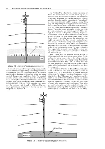
Figure 1.4 A sketch of a gas-cap drive reservoir.
to the packer).
Most wells produce oil through tubing strings, mainly The equipment at the top of the producing wellhead is
because a tubing string provides good sealing performance called a ‘‘Christmas tree’’ (Fig. 1.10) and it is used to
and allows the use of gas expansion to lift oil. The Ameri- control flow. The ‘‘Christmas tree’’ is installed above the
can Petroleum Institute (API) defines tubing size using tubing head. An ‘‘adaptor’’ is a piece of equipment used to
nominal diameter and weight (per foot). The nominal join the two. The ‘‘Christmas tree’’ may have one flow
diameter is based on the internal diameter of the tubing outlet (a tee) or two flow outlets (a cross). The master
body. The weight of tubing determines the tubing outer valve is installed below the tee or cross. To replace a master
diameter. Steel grades of tubing are designated H-40, J-55, valve, the tubing must be plugged. A Christmas tree consists
C-75, L-80, N-80, C-90, and P-105, where the digits repre- of a main valve, wing valves, and a needle valve. These valves
sent the minimum yield strength in 1,000 psi. The min- are used for closing the well when needed. At the top of the
imum performance properties of tubing are given in tee structure (on the top of the ‘‘Christmas tree’’), there is a
Chapter 9 and Appendix B. pressure gauge that indicates the pressure in the tubing.
Oil and Gas
Reservoir
Figure 1.5 A sketch of a dissolved-gas drive reservoir.