
Page 20 - Petroleum Production Engineering, A Computer-Assisted Approach
P. 20
Guo, Boyun / Computer Assited Petroleum Production Engg 0750682701_chap01 Final Proof page 8 4.1.2007 6:12pm Compositor Name: SJoearun
1/8 PETROLEUM PRODUCTION ENGINEERING FUNDAMENTALS
Casing Hanger
Bowl
Hanger Bowl
Production Seal
Casing Tubing Head
Casing
Head
Surface
Casing
Tubing
Figure 1.8 A sketch of a casing head.
Figure 1.9 A sketch of a tubing head.
either the second (backup) master valve or a wing valve.
Again, when the hissing sound stops, the valve is
opened wide. 1.4 Separator
3. The operator opens the other downstream valves the
same way. The fluids produced from oil wells are normally complex
4. To read the tubing pressure gauge, the operator must mixtures of hundreds of different compounds. A typical
open the needle valve at the top of the Christmas tree. oil well stream is a high-velocity, turbulent, constantly
After reading and recording the pressure, the operator expanding mixture of gases and hydrocarbon liquids, in-
may close the valve again to protect the gauge. timately mixed with water vapor, free water, and some-
times solids. The well stream should be processed as soon
The procedure for ‘‘shutting-in’’ a well is the opposite of as possible after bringing them to the surface. Separators
the procedure for opening a well. In shutting-in the well, are used for the purpose.
the master valve is closed last. Valves are closed rather Three types of separators are generally available from
rapidly to avoid wearing of the valve (to prevent erosion). manufacturers: horizontal, vertical, and spherical sep-
At least two valves must be closed. arators. Horizontal separators are further classified into
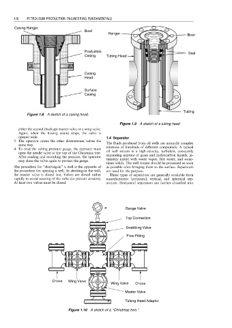
Gauge Valve
Top Connection
Swabbing Valve
Flow Fitting
Choke Wing Valve
Wing Valve Choke
Master Valve
Tubing Head Adaptor
Figure 1.10 A sketch of a ‘‘Christmas tree.’’