
Page 17 - Petroleum Production Engineering, A Computer-Assisted Approach
P. 17
Guo, Boyun / Computer Assited Petroleum Production Engg 0750682701_chap01 Final Proof page 5 4.1.2007 6:12pm Compositor Name: SJoearun
PETROLEUM PRODUCTION SYSTEM 1/5
4,000 solution in the oil (and water). The reservoir gas is actually
Gas Reservoirs
Retrograde in a liquid form in a dissolved solution with the liquids (at
Condensate atmospheric conditions) from the reservoir. Compared to
3,500
Reservoirs the water- and gas-drive reservoirs, expansion of solution
(dissolved) gas in the oil provides a weak driving mech-
anism in a volumetric reservoir. In the regions where the
Reservoir Pressure (psia) 2,500 p tf , T tf 40% p wf , T wf Dew Point escapes from the oil and oil–gas two-phase flow exists. To
p i , T
3,000
Critical
oil pressure drops to below the bubble-point pressure, gas
Point
Bubble
improve oil recovery in the solution-gas reservoir, early
Point
pressure maintenance is usually preferred.
80%
2,000
1.3 Well
20%
1,500
The large-diameter borehole section is at the top of the
well. Each section is cased to the surface, or a liner is
placed in the well that laps over the last casing in the
1,000 Liquid Volume 10% Cricondentherm Point Oil and gas wells are drilled like an upside-down telescope.
5% 0% well. Each casing or liner is cemented into the well (usually
up to at least where the cement overlaps the previous
500 cement job).
0 50 100 150 200 250 300 350 The last casing in the well is the production casing
Reservoir Temperature ( F) (or production liner). Once the production casing has
been cemented into the well, the production tubing is run
Figure 1.2 A typical hydrocarbon phase diagram. into the well. Usually a packer is used near the bottom of
the tubing to isolate the annulus between the outside of the
In a gas-cap drive reservoir, gas-cap drive is the drive tubing and the inside of the casing. Thus, the produced
mechanism where the gas in the reservoir has come out of fluids are forced to move out of the perforation into the
solution and rises to the top of the reservoir to form a gas bottom of the well and then into the inside of the tubing.
cap (Fig. 1.4). Thus, the oil below the gas cap can be Packers can be actuated by either mechanical or hydraulic
produced. If the gas in the gas cap is taken out of the mechanisms. The production tubing is often (particularly
reservoir early in the production process, the reservoir during initial well flow) provided with a bottom-hole
pressure will decrease rapidly. Sometimes an oil reservoir choke to control the initial well flow (i.e., to restrict over-
is subjected to both water and gas-cap drive. production and loss of reservoir pressure).
A dissolved-gas drive reservoir (Fig. 1.5) is also called a Figure 1.6 shows a typical flowing oil well, defined as a
‘‘solution-gas drive reservoir’’ and ‘‘volumetric reservoir.’’ well producing solely because of the natural pressure of the
The oil reservoir has a fixed oil volume surrounded by no- reservoir. It is composed of casings, tubing, packers,
flow boundaries (faults or pinch-outs). Dissolved-gas drive down-hole chokes (optional), wellhead, Christmas tree,
is the drive mechanism where the reservoir gas is held in and surface chokes.
Oil
WOC
Water
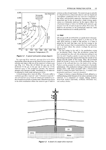
Figure 1.3 A sketch of a water-drive reservoir.