
Page 19 - Petroleum Production Engineering, A Computer-Assisted Approach
P. 19
Guo, Boyun / Computer Assited Petroleum Production Engg 0750682701_chap01 Final Proof page 7 4.1.2007 6:12pm Compositor Name: SJoearun
PETROLEUM PRODUCTION SYSTEM 1/7
in the line. The back-pressure (caused by the chokes or
other restrictions in the flowline) increases the bottom-
hole flowing pressure. Increasing the bottom-hole flowing
pressure decreases the pressure drop from the reservoir to
the wellbore (pressure drawdown). Thus, increasing the
back-pressure in the wellbore decreases the flow rate
Wellhead from the reservoir.
In some wells, chokes are installed in the lower section
of tubing strings. This choke arrangement reduces well-
head pressure and enhances oil production rate as a result
of gas expansion in the tubing string. For gas wells, use of
Surface Casing down-hole chokes minimizes the gas hydrate problem in
Intermediate Casing the well stream. A major disadvantage of using down-hole
chokes is that replacing a choke is costly.
Cement
Production Casing Certain procedures must be followed to open or close a
Annulus well. Before opening, check all the surface equipment such
as safety valves, fittings, and so on. The burner of a line
heater must be lit before the well is opened. This is neces-
Wellbore Tubing sary because the pressure drop across a choke cools the
fluid and may cause gas hydrates or paraffin to deposit
out. A gas burner keeps the involved fluid (usually water)
Bottom-hole Choke hot. Fluid from the well is carried through a coil of piping.
The choke is installed in the heater. Well fluid is heated
Packer both before and after it flows through the choke. The
upstream heating helps melt any solids that may be present
Casing Perforation in the producing fluid. The downstream heating prevents
Reservoir hydrates and paraffins from forming at the choke.
Oil Reservoir
Surface vessels should be open and clear before the well
is allowed to flow. All valves that are in the master valve
Figure 1.6 A sketch of a typical flowing oil well.
and other downstream valves are closed. Then follow the
following procedure to open a well:
The wing valves and their gauges allow access (for pressure 1. The operator barely opens the master valve (just a
measurements and gas or liquid flow) to the annulus crack), and escaping fluid makes a hissing sound.
spaces (Fig. 1.11). When the fluid no longer hisses through the valve, the
‘‘Surface choke’’ (i.e., a restriction in the flowline) is a pressure has been equalized, and then the master valve
piece of equipment used to control the flow rate (Fig. 1.12). is opened wide.
In most flowing wells, the oil production rate is altered by 2. If there are no oil leaks, the operator cracks the next
adjusting the choke size. The choke causes back-pressure downstream valve that is closed. Usually, this will be
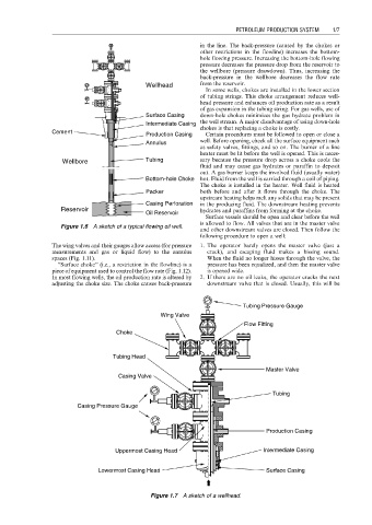
Tubing Pressure Gauge
Wing Valve
Flow Fitting
Choke
Tubing Head
Master Valve
Casing Valve
Tubing
Casing Pressure Gauge
Production Casing
Uppermost Casing Head Intermediate Casing
Lowermost Casing Head Surface Casing
Figure 1.7 A sketch of a wellhead.